Starting a new amp - K50 variant with 6V6s

Express, Liverpool, Rocket, Dirty Little Monster, etc.

Moderators: pompeiisneaks, Colossal

User avatar
Ken Moon
Posts: 610
Joined: Tue May 08, 2007 2:41 pm
Location: Denver

Starting a new amp - K50 variant with 6V6s

Post by Ken Moon »

I'm going to post some pics here of this amp as I go along, since some of you guys were so helpful to me when I was looking for info on the K50 preamp. Thanks especially to Mark for looking over my preamp layout :)

This is going to be a 20-watt version of the K50 Concorde amp, but with a simple cathode-biased, non-NFB 2 x 6V6 power amp (from the Talon amp).

The preamp will be unchanged from the K50, but laid out with the preamp tubes up front and power tubes in the back.

I'll be using a capacitance multiplier-based psu that mimics the CLCLC filter in the Talon psu, but using SS components.

The 47R series resistors on the PT HT secondary is something I'll tweak by ear for a musical-sounding amount of sag.

I'll be using a 'global star' grounding scheme, with the local stars at each filter cap's negative terminal, which are placed right next to their associated circuitry.

I'm also using a separate 6.3vct filament transformer, with an elevated humdinger :shock: for the preamp heaters, and using the heater winding from the big PT for the power tubes (elevated to the 6V6 cathode voltage).

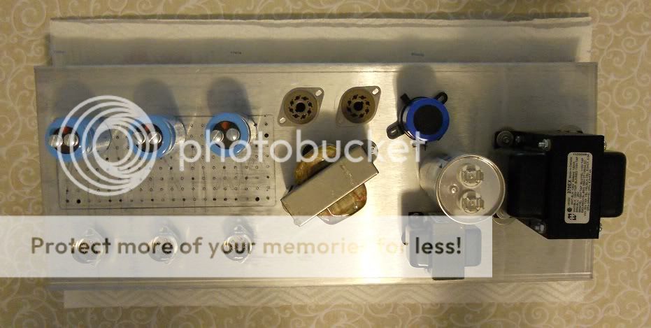
Here is a fit check picture of the top of the amp - I mounted the PT, then used the headphone trick to find the best OT position (I actually found 2 positions that were dead quiet - this one looked the best).

[IMG:931:469]http://i514.photobucket.com/albums/t346 ... eck_sm.jpg[/img]

Here's a sketch of the preamp layout (the tone stack will be mounted on the pots, and I decided to go with the Mallory can caps):
[IMG:1023:749]http://i514.photobucket.com/albums/t346 ... layout.jpg[/img]
Here's the psu schematic - I expect a B+ of about 375V at the 6V6 plates (I also decided to use a 40uF/440VAC motor run cap for the reservoir):
[IMG:863:657]http://i514.photobucket.com/albums/t346 ... K20psu.jpg[/img]

Here's a link to the Talon schematic for reference:

http://moonguitaramps.com/images/talon_schematic.png

edit: I'm still working on a full schematic and layout - I'll post them as soon as I get them done :oops:
User avatar
dave g
Posts: 383
Joined: Fri Aug 10, 2007 11:34 pm
Location: Cambridge, MA

Re: Starting a new amp - K50 variant with 6V6s

Post by dave g »

Just an observation, if you want to preserve the clean to mean characteristics of the K50, it would be better to use a fixed bias output section.
User avatar
Ken Moon
Posts: 610
Joined: Tue May 08, 2007 2:41 pm
Location: Denver

Re: Starting a new amp - K50 variant with 6V6s

Post by Ken Moon »

Thanks, Dave :)

That was originally what the whole Talon experiment was for me - can you get the fast attack and lack of note smearing that's easy enough to do with fixed bias, but with cathode bias - and I found that I could, if I keep the psu stiff, fast and clean, limit the bass response through the early amp stages, and use no global NFB.

I'll tune in the desired amount of sag using the HT series resistors (I use a homemade dual 500r/50w rheostat to tweak this), to match the original K50 response as best as I can, then tweak to taste from there.

And I always try to have an "original" on hand to compare, so I'm building an ugly but working stock K50 with EL34s on another chassis to A/B with (when doing the Talon, I had a late-70's 2204 and an Express clone I built, since I was going for something in the range of those sounds).
John_P_WI
Posts: 1456
Joined: Wed Aug 15, 2007 4:29 pm
Location: Wisconsin

Re: Starting a new amp - K50 variant with 6V6s

Post by John_P_WI »

Ken,

I am greatly interested in how the gyrator circuit is working for you. This would be a great solution for small SE amps.

Is any (small, 100 ohms or so) resistance needed between the plate and screen gyrator?

Thanks again, this is very interesting and I am curious as to how you like it.

John
User avatar
Ken Moon
Posts: 610
Joined: Tue May 08, 2007 2:41 pm
Location: Denver

Re: Starting a new amp - K50 variant with 6V6s

Post by Ken Moon »

Thanks!

No, it's not necessary, but a series resistor can be added in between the filter stages, but there are other ways to control the screen voltage too - you can put another resistor between R4 and ground, forming a voltage divider at the base of Q4 (for example, you could use 1k for R4 and 10k for the new resistor, and the screen voltage will track to about 90 percent of the plate voltage).

Or, you could put a string of zeners from the base of Q4 to ground, and set the screen voltage at any voltage up to a couple of volts below the plate voltage.

I swiped this circuit from Merlin, and he has a whole section on cap multipliers and other cool circuits in his new power supply book:

http://www.amazon.com/Designing-Power-S ... 0956154514

A cap multiplier was also used on the UberSEL amp over at AX84:

http://ax84.com/ubergain.html
surfsup
Posts: 1513
Joined: Mon Nov 29, 2010 12:21 am
Location: Chicagoland

Re: Starting a new amp - K50 variant with 6V6s

Post by surfsup »

that coupling cap switch between V1 and V2, if you don't mind my asking, that varies the resistance between 100k or 22k and the difference resistance will affect the frequency of signal passed based on this formula:

f=1/(6.28CR)

So you have a switchable -3db frequency of 72Hz or 16Hz to remove some bass, correct?
John_P_WI
Posts: 1456
Joined: Wed Aug 15, 2007 4:29 pm
Location: Wisconsin

Re: Starting a new amp - K50 variant with 6V6s

Post by John_P_WI »

Cool, thanks Ken.

Good to see some new ideas being used to move forward.

Thanks for links too,

John
User avatar
Ken Moon
Posts: 610
Joined: Tue May 08, 2007 2:41 pm
Location: Denver

Re: Starting a new amp - K50 variant with 6V6s

Post by Ken Moon »

surfsup wrote:that coupling cap switch between V1 and V2, if you don't mind my asking, that varies the resistance between 100k or 22k and the difference resistance will affect the frequency of signal passed based on this formula:

f=1/(6.28CR)

So you have a switchable -3db frequency of 72Hz or 16Hz to remove some bass, correct?
Sorry I missed this :oops:

That's the fast/gradual switch, which implements a split load on the V1a plate.

In Fast mode it works the same as if there was a 100k plate resistor, and in Gradual mode, it's like having a 100k pot for the plate resistor (with the following 0.1uF cap connected to the wiper) , and tapping the AC output at 22 percent of it's total swing (22k/100k).

The preamp stage bias stays the same, but the AC signal going to the next stage is attenuated, lowering gain and noise.

Some folks replace the 0.1 cap after the switch with a lower value - I can't remember what that does for you :?

From the clips I've heard, I'm thinking I might remove the switch and go with a fixed split load, but more like 50-50, since the Gradual sounds a bit cool and the Fast a bit hot (to me).
User avatar
M Fowler
Posts: 14019
Joined: Wed Jan 16, 2008 2:19 am
Location: Walcott ND

Re: Starting a new amp - K50 variant with 6V6s

Post by M Fowler »

Ken I agree that fast engaged is too hot. I was wondering if anyone else thought the same.

Mark
User avatar
Colossal
Posts: 5059
Joined: Sat Oct 20, 2007 9:04 pm
Location: Moving through Kashmir

Re: Starting a new amp - K50 variant with 6V6s

Post by Colossal »

Ken Moon wrote:Some folks replace the 0.1 cap after the switch with a lower value - I can't remember what that does for you :?
It tightens up the bass considerably. At higher volume, the low end gets flabby (probably blocking distortion). Dave Friedman (I believe) modded both of Pete Thorn's K50s to 0.01 (or even 0.001uF). There is a thread on it where Allyn Meyers confirms the result.
User avatar
Colossal
Posts: 5059
Joined: Sat Oct 20, 2007 9:04 pm
Location: Moving through Kashmir

Re: Starting a new amp - K50 variant with 6V6s

Post by Colossal »

M Fowler wrote:Ken I agree that fast engaged is too hot. I was wondering if anyone else thought the same.

Mark
I have not played a K50 but from the demo clips available, I much prefer Gradual mode.
passfan
Posts: 1353
Joined: Sun Jan 10, 2010 2:01 pm
Location: Central Florida

Re: Starting a new amp - K50 variant with 6V6s

Post by passfan »

M Fowler wrote:Ken I agree that fast engaged is too hot. I was wondering if anyone else thought the same.

Mark
I like the "attack" of it but yes , I always back it down in fast mode, less than what I run in gradual.
"It Happens"
Forrest Gump
User avatar
Ken Moon
Posts: 610
Joined: Tue May 08, 2007 2:41 pm
Location: Denver

Re: Starting a new amp - K50 variant with 6V6s

Post by Ken Moon »

Passfan,

Do you have to back the guitar volume down some, even with single coils, when in Fast mode?

I've been digging my strat again lately, since I put a Suhr V60 pickup in the neck position - do you think a vintage-style single coil has enough output in Gradual mode to sound decent?

The only thing that worries me about deleting the switch entirely is whether or not the amp will sound good with a range of pickups :?
passfan
Posts: 1353
Joined: Sun Jan 10, 2010 2:01 pm
Location: Central Florida

Re: Starting a new amp - K50 variant with 6V6s

Post by passfan »

Ken Moon wrote:Passfan,

Do you have to back the guitar volume down some, even with single coils, when in Fast mode?

I've been digging my strat again lately, since I put a Suhr V60 pickup in the neck position - do you think a vintage-style single coil has enough output in Gradual mode to sound decent?

The only thing that worries me about deleting the switch entirely is whether or not the amp will sound good with a range of pickups :?
Not with the Tele, but there is a volume difference. I don't spend enough time in fast mode around the house. I don't really want to go to jail or get hit with another shoe. With a humbucker it's too loud to get up around distortion in either mode. I have to take it to the studio for that. The gradual on around 12 o'clock with the Tele is really nice and creamy with little to no breakup. As the weekends roll by (more studio time) I will have more time to become acquainted with it's quirks, or lack thereof. As for to switch, or not to switch, I could play it all day (either Tele or V) in gradual mode. 2 o'clock with my V really kicks butt. 2 o'clock in fast mode with my V and I wouldn't stand in front for very long. Your running 20 watts with 6V6's, I'm running full power with 6L6GC's. Try to factor that in... not much help huh? :(
"It Happens"
Forrest Gump
User avatar
Ken Moon
Posts: 610
Joined: Tue May 08, 2007 2:41 pm
Location: Denver

laying out the cap multiplier psu board

Post by Ken Moon »

I've been struggling with how to build the psu for this amp, and decided that PCB is the way to go, with the TO-220 components. Here's a layout that puts a single darlington-pair cap multiplier stage on a round PCB that mounts on 4 bolts, 2" apart (board is 2.5 inches diameter).

It will take 2 of these boards for the complete psu, so I was thinking of stacking them vertically - I even found these cool little round vent covers - with one of those and a short piece of 2.5-inch diameter Delrin pipe, I could make a little hockey-puck looking device that would replace one or even 2 chokes.

Excuse my hand-drawn layout - I'll put in in Eagle PCB next week at work, so I can send the gerber files out to get the boards made. If they turn out nice, I'll be glad to share the gerber files.

I also added the portion of the schematic that is on the PCB board (C3 is an off-board filter cap, so it's not on the PCB).

[IMG:953:937]http://i514.photobucket.com/albums/t346 ... ndraft.jpg[/img]
[IMG:922:692]http://i514.photobucket.com/albums/t346 ... tcover.jpg[/img]
[IMG:922:692]http://i514.photobucket.com/albums/t346 ... hem_sm.png[/img]
Post Reply