
I am using the A1a version schematic. I have the power supply section in layout form and the preamp layout (thanks to the good people here). What I need is the power amp section in layout for to complete my amp. anyone care to help?
Allynmey
Power amp section layout for A1A version schematic
Moderators: pompeiisneaks, Colossal
-
Jackie Treehorn
- Posts: 236
- Joined: Thu Jan 20, 2005 4:54 pm
- Location: New Orleans, LA
Re: Power amp section layout for A1A version schematic
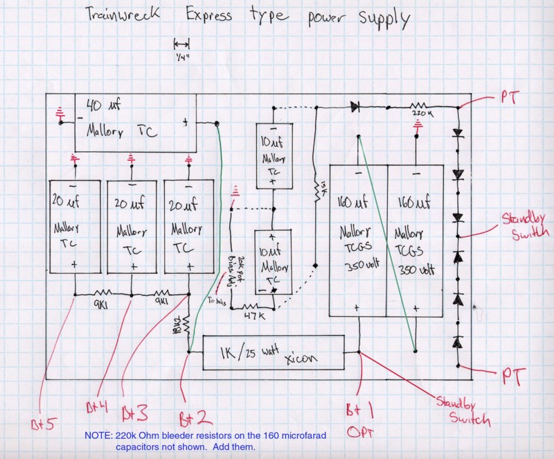
I finally dug out my power supply layout from my other computer. The values for the resistors in the bias supply are from the A1A schematic and it has been noted that they result in not enough bias voltage. Someone has posted better values somewhere... Sprague Atoms are too large to use in this layout without some serious adjusting.
-
Jackie Treehorn
- Posts: 236
- Joined: Thu Jan 20, 2005 4:54 pm
- Location: New Orleans, LA
Re: Power amp section layout for A1A version schematic
Ahh, I misunderstood and thought we were talking power SUPPLY! Oh well. Maybe someone else will find my previous post interesting...
Re: Power amp section layout for A1A version schematic
I'm definitely not complaining! Thanks for the drawing... gotta wonder if you made any other layout sketches...
Thanks for the post!
Thanks for the post!
Re: Power amp section layout for A1A version schematic
Thanks for the reply Jackie 
I have a power supply layout that Snide put together. I'll add it below. I understand that...don't flame me everyone!... that the a1a version in the sites files is the closest to the original. Maybe I'm wrong. It would be helpful if we had a full layout done with visio or Acrobat of the entire layout from input jack to output jack for relative numbskulls like me to follow. I've built my first 18 Watt TMB and it rocks, but, I still consider myself a newbie to circuit theory and amp design. Anyone have such a layout?Thanks all,
Allynmey
You do not have the required permissions to view the files attached to this post.