TC-15 - should I complicate it?

Vox and Hiwatt Discussion

Moderators: pompeiisneaks, Colossal

Post Reply
alathIN
Posts: 10
Joined: Thu Oct 11, 2018 5:00 pm

TC-15 - should I complicate it?

Post by alathIN »

Gearing up for my first build - a Trinity TC15. Yes, I know it's kind of complex for a first amp build. I'm not an experienced amp builder but I'm experienced at taking on complicated projects that I'm unqualified for 8)

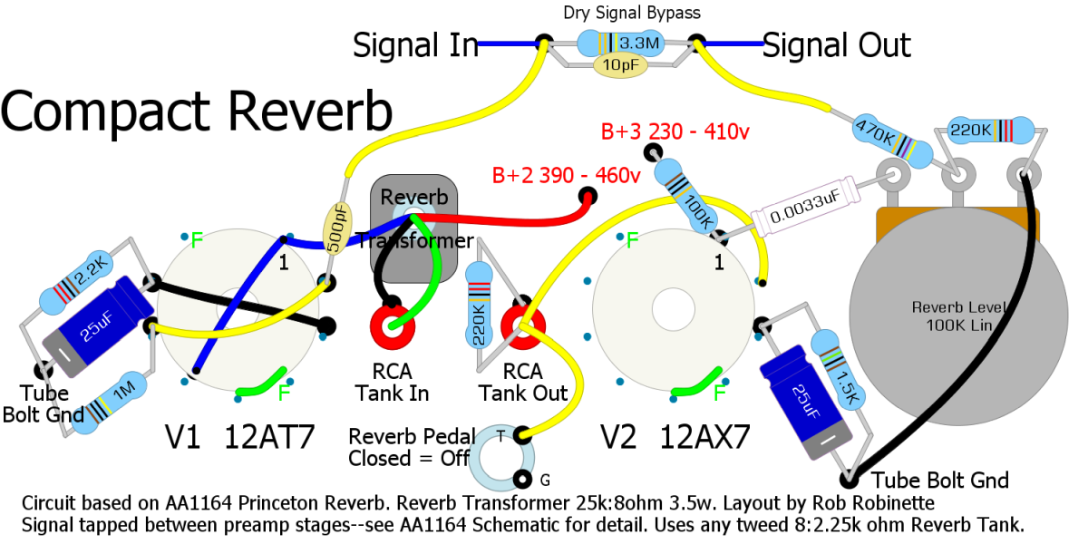
I'm debating whether to complicate this further by adding on a spring reverb, probably this or something like it:

Image

Here's the TC15 schematic
Image

Pro: This will likely be my only amp for a long time, why leave any regrets? I use reverb a lot - usually subtle - but almost never play with zero 'verb
Con: Adding complexity and expense to the build, needing to find real estate on the panel for a reverb control, needing to build my cabinet bigger (not a huge deal I guess)
Wild Card: There are plenty of reverb pedals out there - but haven't found my "dream reverb"
User avatar
Guy77
Posts: 915
Joined: Sat May 31, 2014 2:46 am
Location: Toronto, Canada

Re: TC-15 - should I complicate it?

Post by Guy77 »

Hi.
I have added that reverb from the same layout posted and it sounded fine. I placed the input side just after the return loop and connected the output side right were the phase inverter entrance is. ( where you would normally connect the return from the effects loop on a dumble style amp or where the Master volume would connect too on an amp with no effects loop).
It can be a little tricky to find the real estate to add this and of course its always easier to just add a pedal but its a fun project and the reverb sounded nice and full.

If this is your first amp build you may want to keep things simple and maybe just leave some room to add this reverb later after you have built the initial amp.

The only change I made was to change the mixer 3.3M resistor to a 700K resistor with no 10pf capacitor connected. You can always adjust that to taste, too high a value will effect the clean tone in a negative way.


Cheers

Guy
alathIN
Posts: 10
Joined: Thu Oct 11, 2018 5:00 pm

Re: TC-15 - should I complicate it?

Post by alathIN »

Guy77 wrote: Mon Oct 15, 2018 10:24 pm If this is your first amp build you may want to keep things simple and maybe just leave some room to add this reverb later after you have built the initial amp.

The only change I made was to change the mixer 3.3M resistor to a 700K resistor with no 10pf capacitor connected. You can always adjust that to taste, too high a value will effect the clean tone in a negative way.
Good idea: make the larger cabinet, but leave the reverb for a later add-on project. Best of both worlds. Besides, it would be a tragedy to run out of projects ;-)

I wasn't anticipating trying to cram this in on the same chassis. I have access to a metal fabricating shop, so my first thought was to make a separate mini-chassis just for the reverb circuit.

Appreciate the resistor change tip. Messing up the native clean tone is the last thing I want to do.

Is there any concern about adding this extra current draw that the good folks at Trinity were not anticipating when they spec'd the power transformer?
User avatar
pompeiisneaks
Site Admin
Posts: 4222
Joined: Sat Jan 14, 2017 4:36 pm
Location: Washington State, USA
Contact:

Re: TC-15 - should I complicate it?

Post by pompeiisneaks »

You definitely need to look into the heater current capability of the PT. Adding an additional tube adds about 300mA of additional current, and most amps have the heaters near their limit already. Just double check to be sure. Doesn't mean you can't just buy a separate 6.3V transformer and slap that inside the chassis to provide the reverb tube the extra current it needs. As for the rest of that tube it only needs a few 10-30mA for the actual operation of the anode-cathode of the tube so the mains should likely be okay, unless they vastly under specced that.

~Phil
tUber Nerd!
Stevem
Posts: 4576
Joined: Fri Jan 24, 2014 3:01 pm
Location: 1/3rd the way out one of the arms of the Milkyway.

Re: TC-15 - should I complicate it?

Post by Stevem »

So how have your previously unqualified projects turned out?

You really may need a different power transformer for the added reverb circuit since that parallel plate plate 12AT7 pulls a lot more current a may/ will tax the power transformer a good bit more if it was on the edge of what was needed to begin with!

Do you know how to figure out a amps HT current demands ?
When I die, I want to go like my Grandfather did, peacefully in his sleep.
Not screaming like the passengers in his car!😊

Cutting out a man's tongue does not mean he’s a liar, but it does show that you fear the truth he might speak about you!
alathIN
Posts: 10
Joined: Thu Oct 11, 2018 5:00 pm

Re: TC-15 - should I complicate it?

Post by alathIN »

Stevem wrote: Wed Oct 17, 2018 1:35 pm Do you know how to figure out a amps HT current demands ?
No. Do you have a good link or resource for this?

Re, unqualified projects - all successful. Usually have some "bonus" hassles and re-dos. My general pattern is that by the end of the project, I know what I should have known at the beginning.
alathIN
Posts: 10
Joined: Thu Oct 11, 2018 5:00 pm

Re: TC-15 - should I complicate it?

Post by alathIN »

pompeiisneaks wrote: Tue Oct 16, 2018 3:54 pm You definitely need to look into the heater current capability of the PT. Adding an additional tube adds about 300mA of additional current, and most amps have the heaters near their limit already. Just double check to be sure. Doesn't mean you can't just buy a separate 6.3V transformer and slap that inside the chassis to provide the reverb tube the extra current it needs. As for the rest of that tube it only needs a few 10-30mA for the actual operation of the anode-cathode of the tube so the mains should likely be okay, unless they vastly under specced that.

~Phil
So I'm thinking about how to do this without transformers becoming fruitful and multiplying in Biblical proportions :P

Maybe substitute a higher capacity PT?

If I add another 6.3v transformer then I'd need another rectifier because the reverb transformer and the tubes downstream of it aren't going to want AC, correct?

Could I substitute a different reverb transformer that would take me from wall current to what the reverb tubes want? I'd still need another rectifier (I think), but then at least I wouldn't have in effect two power transformers plus a reverb transformer.
User avatar
pompeiisneaks
Site Admin
Posts: 4222
Joined: Sat Jan 14, 2017 4:36 pm
Location: Washington State, USA
Contact:

Re: TC-15 - should I complicate it?

Post by pompeiisneaks »

The reverb transformer just takes the reverb signal and changes it's impedance to match the tank. Nothing to do with the tubes themselves.

To calculate the needs of hte transformer, you look at the secondary windings and see how much current they need by adding up all the required current draw of all devices on that chain.

Example, a 12AX7 requires 300mA of current for the heaters and about 1 mA or so for the anode-cathode operation (depending on plate voltages). You can get all of these for any specific tube from the tube datasheet. Then you just count up the number of that tube and add up it's current needs and repeat for all tube types. Say power tubes were 6L6GC's .9A current for the heaters, 66mA at max operation for the one I looked up for the plate-cathode operation.

So if you say had 4X6l6gc tubes and 4x12AX7 tubes in an amp, you'd need:

12AX7
.300 X 4 = 1.2A heaters
.001 X 4 = .004A B+ current
6L6GC
.9 X 4 = 3.6A heaters
.066 X 4 = 0.264A current B+

This means if you add all of that up, you'd need 4.8 A capacity for the heater winding, and about 300mA for the B+ winding.

So you'd need to do a similar add up for your amp, figure out how much you need, and make sure you have it. It's also good to go a touch over for two reasons:

1. when things are running cooler, they last longer
2. you may want to add more to the amp later, so extra ampacity is a bonus.

~Phil
tUber Nerd!
alathIN
Posts: 10
Joined: Thu Oct 11, 2018 5:00 pm

Re: TC-15 - should I complicate it?

Post by alathIN »

TC-15
12AX7 x 3
.300 x 3 = .900 heaters
.001 x 3 = .004 B+
EL84 x 2
.760 x 2 = 1.52 heaters
.048 x 2 = .098 B+
EF86 x 1
.200 x 1 = .200 heater
.003 x 1 = .003 B+
5AR4 x 1
1.9 = heater
.250 = B+
Reverb
12AT7
.300 = heater
0.010 = B+
12ax7
.300 + heater
0.001 = B+

Heaters: 5.12 mA
B+ - 0.336

Sorry, doing my calculations on the forum ;-)
sluckey
Posts: 3079
Joined: Sun Jul 22, 2007 7:48 pm
Location: Mobile, AL
Contact:

Re: TC-15 - should I complicate it?

Post by sluckey »

The 5AR4 is not counted in this calculation.

I would be surprised if the PT can't handle an extra .6A filament current. But all this calculating gets nowhere if you don't know the capacity of the Trinity PT. Why not just ask the good guys at Trinity if that PT can support a Fender two tube reverb circuit?
User avatar
pompeiisneaks
Site Admin
Posts: 4222
Joined: Sat Jan 14, 2017 4:36 pm
Location: Washington State, USA
Contact:

Re: TC-15 - should I complicate it?

Post by pompeiisneaks »

Yeah the 5AR4 uses the 5V taps and uses that current available. I agree with Sluckey too, it may be simpler to just ask what it can handle.

~Phil
tUber Nerd!
alathIN
Posts: 10
Joined: Thu Oct 11, 2018 5:00 pm

Re: TC-15 - should I complicate it?

Post by alathIN »

Was in touch with Steven @ Trinity.
He said .6A is manageable;. Also pointed me at a thread on the Trinity forum where someone has tried something like this.
Thanks for all of your suggestions. I learned something from this.

I was wondering whether the rectifier tube should really be counted in the addition, but I figured it's better to addict and have too much capacity then not and have a problem.

Thanks again!
Stevem
Posts: 4576
Joined: Fri Jan 24, 2014 3:01 pm
Location: 1/3rd the way out one of the arms of the Milkyway.

Re: TC-15 - should I complicate it?

Post by Stevem »

6.3 volt heater current wise you really do not want to have more then a extra 1/2 amp on hand.
If you do the voltage will be up closer to 7 and that will stress the filiments some and increase your preamp gain to harsh sounding levels if your tubes are really good!
When I die, I want to go like my Grandfather did, peacefully in his sleep.
Not screaming like the passengers in his car!😊

Cutting out a man's tongue does not mean he’s a liar, but it does show that you fear the truth he might speak about you!
pdf64
Posts: 2702
Joined: Sat Mar 12, 2011 9:23 pm
Location: Staffordshire, UK

Re: TC-15 - should I complicate it?

Post by pdf64 »

Guy77 wrote: Mon Oct 15, 2018 10:24 pm...I have added that reverb from the same layout posted and it sounded fine. I placed the input side just after the return loop and connected the output side right were the phase inverter entrance is...
But both inputs of the LTP phase splitter are used, one for each channel :?
So unless something else is changed, only one of the channels could get 'reverbed'.
alathIN
Posts: 10
Joined: Thu Oct 11, 2018 5:00 pm

Re: TC-15 - should I complicate it?

Post by alathIN »

pdf64 wrote: Sat Oct 27, 2018 1:07 pm
Guy77 wrote: Mon Oct 15, 2018 10:24 pm...I have added that reverb from the same layout posted and it sounded fine. I placed the input side just after the return loop and connected the output side right were the phase inverter entrance is...
But both inputs of the LTP phase splitter are used, one for each channel :?
So unless something else is changed, only one of the channels could get 'reverbed'.
There's an old discussion of this on the Trinity site (doesn't seem to be very active for current questions).

The consensus was there is no very good way to put reverb on both channels. The guys who did it put the reverb on the EF86 channel, then used a jumper if they wanted some of the 12ax7 tones going through the reverb.
Post Reply