AC4 project
Moderators: pompeiisneaks, Colossal
-
martin manning

- Posts: 13207
- Joined: Sun Jul 06, 2008 12:43 am
- Location: 39°06' N 84°30' W
Re: AC4 project
The resistors and caps in the cathode circuit are doing some frequency response shaping on that stage, cutting some bass relative to a fully bypassed 1k5//22u arrangement. A similar effect could be achieved by reducing the coupling cap at the plate, which is now a rather large 100n.
-
martin manning
- Posts: 13207
- Joined: Sun Jul 06, 2008 12:43 am
- Location: 39°06' N 84°30' W
Re: AC4 project
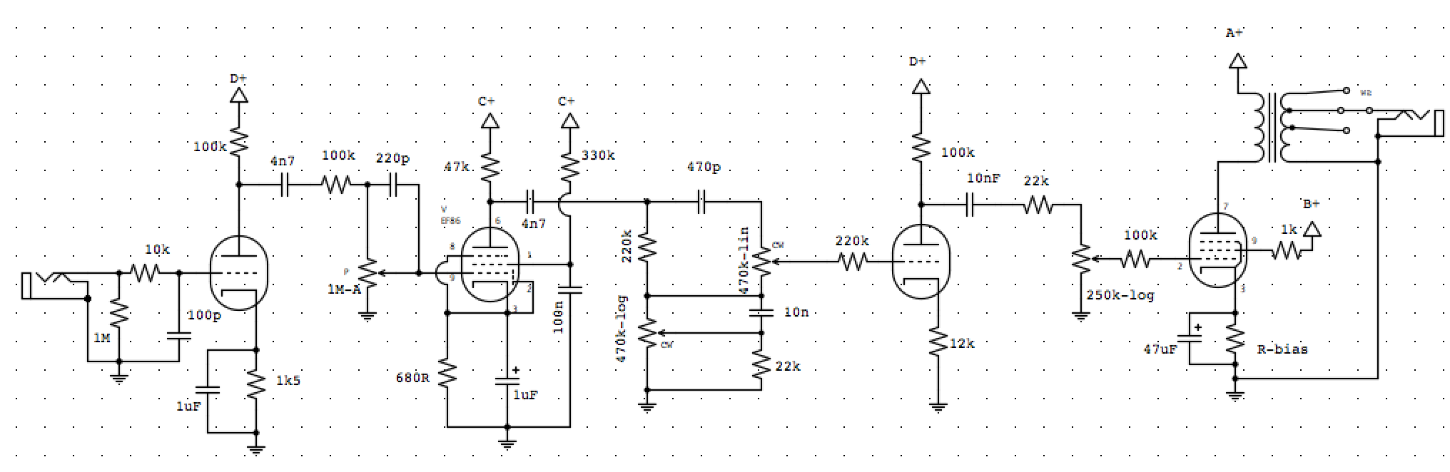
To add another channel, I'd do it this way. You can easily try shorting R12/C8 to see what restoring the low end does. You could put a switch there too, if it's useful.
You do not have the required permissions to view the files attached to this post.

Re: AC4 project
It was this comment on TDPRI that made me realise there might be a problem with simply adding an other channel like in the schematic.
My question as why the caps is more relating to the arrangement with two resistors and caps in series, and the 1M to the grid in between them, and not so much about their size. That is helpful information, nevertheless.
My question as why the caps is more relating to the arrangement with two resistors and caps in series, and the 1M to the grid in between them, and not so much about their size. That is helpful information, nevertheless.
You do not have the required permissions to view the files attached to this post.
-
martin manning
- Posts: 13207
- Joined: Sun Jul 06, 2008 12:43 am
- Location: 39°06' N 84°30' W
Re: AC4 project
No problem at all. Of course I'm assuming that "Ch 3" in my marked-up is like channel 1, where there is a cap blocking DC and a volume pot at its output.
They are related. The 1Meg grid leak is connected below the 1k5 so the bias (Vg-k) is the same as if the 1k5 and 1M were going to ground. The 3k9 below it will raise the Vk a bit (about 3.9V), but the tube only cares about Vg-k. The total load does go up (3k9 gets added to the 100k and the 1k5), but that is of little consequence. It's more about the 3k9//2u2 adding another low frequency roll-off to the one created by the 1k5//10u.
Re: AC4 project
OK, I see. So there's no need to put an extra cap after the volume pot, like in the 2:nd channel?
For clarity: the added channel is ch 1, but I want to move the mixing point so it's before V2b, instead of before the EL84, as in earlier schematics.
I just find the resistors/caps in series arrangement strange instead of just using one smaller cap for the bass reducing effect that you mention. But my understanding of how amplifiers work is quite basic, so far... but I'm learning.
-
martin manning
- Posts: 13207
- Joined: Sun Jul 06, 2008 12:43 am
- Location: 39°06' N 84°30' W
Re: AC4 project
I think C10 is there to keep DC voltage produced by the 3k9 cathode resistor R12 off of pots P3 and P4.
In the AC4 v2 schematic, Ch 1 is mixed with Ch 2 before V2b, so I don't understand your point there.
Re: AC4 project
OK, thanks. So as I understand it, it's safest to either bypass the 3k9 cathode resistor, or putting an extra cap between ch1 pots and mixing point.
I didn't explain that I referred to the AC4 (V1) schematic earlier in this thread, where the channels are mixed just before the EL84.
I didn't explain that I referred to the AC4 (V1) schematic earlier in this thread, where the channels are mixed just before the EL84.
-
martin manning
- Posts: 13207
- Joined: Sun Jul 06, 2008 12:43 am
- Location: 39°06' N 84°30' W
Re: AC4 project
I see, I misunderstood, thinking you wanted to add a third channel, and It wasn't clear to me which parts of the circuit were original and which were your modifications. You can just ignore my "Ch 3" in the marked-up AC4 v2 schematic; it's fine the way it is. If you delete R12 and C8 then you don't need C10. If you do that, you might want to reduce C13.
Re: AC4 project
A bit late at the party ... 
I'm not really competent in the matter, especially when it comes to multi-channel but it seems to me that you've somewhat messing with the inputs.
Firstly: might the 220 pF (C20) to ground be responsible for less signal in the EF86 channel, vs. the 22pF (C21), where they are (before the grid resistor)?
Secondly, it looks like your schematic somewhat clashes with "Merlin Blencowe's pre-amp book" / Section 4.6.
Merlin recommends using smaller grid resistor values (10k, as you did) but in lieu of R1 & R6 (22k), not before, and especially after the grid leak resistors R2 & R7 (1M).
Like that:
(not my own design, NB)
These grid resistors Merlin also recommends that they be possibly connected to the tube socket - so your R26 & R27 might as well disapear...
Possibly I have been missing something (one more time) ...
Nice project by the way...
Re: AC4 project
Honestly I'm kinda shooting in the dark, but I've read up on some stuff and get by with a little help from my friends...
Here are some sound samples:
Made some sound samples of my amp today. I used a free version of an app that only let you export 90 sec of sound, so some are cut at the end... It's recorded with my Telecaster with single coil bridge and neck humbucker in parallel. Cab miced with a Shure SM58 close to the speaker and a AKG P170 about a foot away. Only effect is a slap back delay.
First is the EF86 channel switching between 10n and 2n2 cap (C2a/b):
https://soundcloud.com/oskar-pohjola/1nac4ef8610n2n2cap
Then EF86 with the screen bypass cap out of circuit (which gives less gain, starts getting some distortion at half volume):
https://soundcloud.com/oskar-pohjola/2nac4ef86nocap
Next EF86 (2Cb2n2) and then ECC83 clean(ish) volume just about on:
https://soundcloud.com/oskar-pohjola/3n ... hef86ecc83
EF86 and then ECC83 with volume at about 1/3:
https://soundcloud.com/oskar-pohjola/4n ... -ef86ecc83
And now with the volume dimed (on EF86 about 3/4, since full on makes it squeal and makes an oscillating effect like tremolo when the notes fade.):
https://soundcloud.com/oskar-pohjola/5n ... def86ecc83
https://soundcloud.com/oskar-pohjola/6n ... def86ecc83
https://soundcloud.com/oskar-pohjola/7n ... def86ecc83
The ECC83 channel definitely has more scoped sound.
Re: AC4 project
I experienced this kind of unvoluntary tremolo effect with my first build, which had an EF86 in pre-amp too. It disappeared. Don't know neither why, nor what it was:
- new caps, new EF86, whatever?
Are you filter caps all properly grounded? I remember having that issue, but I'm not sure that was after or before...
NB Your friends helping you make me think of too many people reading the map to find the direction to go to...
- new caps, new EF86, whatever?
Are you filter caps all properly grounded? I remember having that issue, but I'm not sure that was after or before...
NB Your friends helping you make me think of too many people reading the map to find the direction to go to...
Re: AC4 project
Not a problem, I choose the direction! (Even though it might be wrong!!!) 
Re: AC4 project
I just tried the amp with a 12AY7, that I borrowed from the Tweed Deluxe, in V2.
It works really good, I get a little clean sweep on the EF86 channel (about 1/5), then it starts overdriving slightly.
The second channel is clean to about 1/3, and really starts overdriving at 1/2 volume. At full volume you still get that 70's Rock feeling.
If I can't get more headroom by increasing the plate voltage, I think the 12AY7 is the solution. (Still waiting for the resistors I ordered to come before I can start working on that.)