Hi,
given that original ac30s have a power supply where all preamp tubes are feed from the screen filter cap with individual 22k dropping resistors (except for the 10k on cathode follower), what would be the best grounding scheme?
Should all preamp tubes be grounded together in a star ground (seperate from the mains and screen grounds)? Or should one use a multi star ground for the preamp as recommended by Merlin and others?
Optimal Grounding scheme for AC30?
Moderators: pompeiisneaks, Colossal
Optimal Grounding scheme for AC30?
www.myspace.com/20bonesband
www.myspace.com/prostitutes
Express, Comet 60, Jtm45, jtm50, jmp50, 6g6b, vibroverb, champster, alessandro rottweiler
4x12" w/H75s
www.myspace.com/prostitutes
Express, Comet 60, Jtm45, jtm50, jmp50, 6g6b, vibroverb, champster, alessandro rottweiler
4x12" w/H75s
Re: Optimal Grounding scheme for AC30?
I can’t help, but I certainly agree that the earthing leaves a lot to be desired. The preamp earth wanders around various parts of the preamp.
Yours Sincerely
Mark Abbott
Mark Abbott

Re: Optimal Grounding scheme for AC30?
What is complicated?
Current must start and return to one capacitor, dedicated to this stage.
If this is complicated think about battery 1.5V and LED. When you connect a LED on battery there is a light. Cathode of the LED goes to the minus pole of battery.
It is the same with the valves. Valve is a LED and battery is a electrolytic capacitor. Cathode wires connect to that el.capacitor.
You cannot connect output tubes cathode wire to minus pole on the preamp stage! The same for the screens. Also you cannot connect cathode wire of preamp tube to output stage el.capacitor. Never mix the currents in the gnd. And so on.
Then is easy.
Never use the chassis for returning wires. It is out of control then. You need to control currents in the ground return path. Daisy chain of local star gnds is the best for all the amps, also ultra high gain. VOX AC30 is low gain, so makes all easy money.
Re: Optimal Grounding scheme for AC30?
The AC30 doesn’t have a daisy chained HT though.
Rather it radiates out in 4 feeds from the screen grid node.

https://el34world.com/charts/Schematics ... actory.jpg
My band:- http://www.youtube.com/user/RedwingBand
Re: Optimal Grounding scheme for AC30?
preamp:
daisy chain local stars from the top schem>from the input:
1. node 8uF
2. node upper 32uF
3. node PI 8uF
4. tremolo node 32uF all star with all the tubes in tremolo / connected to 1.st node local star/ or second 32uF i would see what is better
daisy chain local stars from the top schem>from the input:
1. node 8uF
2. node upper 32uF
3. node PI 8uF
4. tremolo node 32uF all star with all the tubes in tremolo / connected to 1.st node local star/ or second 32uF i would see what is better
Re: Optimal Grounding scheme for AC30?
So
1 v1? or the first preamp stage
2 cathode follower
3 phase inverter?
www.myspace.com/20bonesband
www.myspace.com/prostitutes
Express, Comet 60, Jtm45, jtm50, jmp50, 6g6b, vibroverb, champster, alessandro rottweiler
4x12" w/H75s
www.myspace.com/prostitutes
Express, Comet 60, Jtm45, jtm50, jmp50, 6g6b, vibroverb, champster, alessandro rottweiler
4x12" w/H75s
Re: Optimal Grounding scheme for AC30?
Haha, the schematic I used is nice and clear but unfortunately lacks any component references, not even V#.
This one may be a better basis for discussion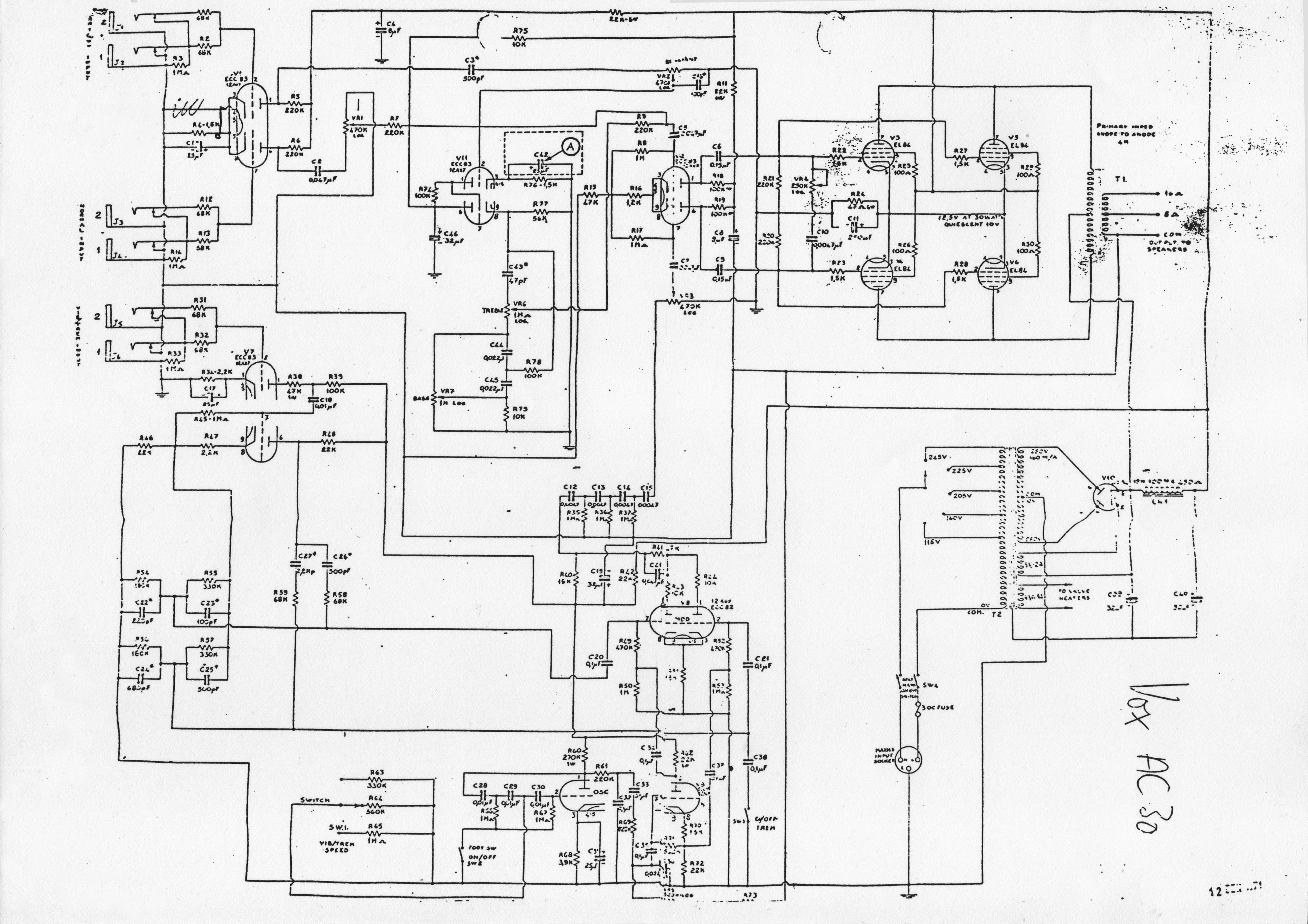
From that, using my understanding of bepone’s post, the first (or last / end) common star point, which would be the only circuit common connection to the chassis metalwork, would be around V1 at ‘C8 R6 C1 J1-4’.
Then wire that to the next star point, for the top boost circuit around V11, at ‘C46 VR2 R76 R77 R75 VR7’.
Then wire that to the star point for the LTP phase splitter around V?, at ‘C8 R15 VR1&3’.
Then wire that to screen grid star node, at C40.
The vib trem channel star based around C19 etc would have its own star, wired either to the C8 or C46 star, whichever worked out best.
Just to be clear, there would be no other circuit common connections to either the pre or power amp chassis metalwork than the C8 star.
IMO it would also be good heater hum mitigation to balance the heater circuit and elevate it (connect the balance point node) to the output valves’ cathode node, at C11//R46.
My band:- http://www.youtube.com/user/RedwingBand
Re: Optimal Grounding scheme for AC30?
This is the layout, the preamp earthing snakes through the various stages. Definitely not a good version of star grounding.
http://turretboard.knucklehead.dk/2012/ ... ca-layout/
The Weber layout is in the link, but you have to select it.
https://www.tedweber.com/6v30-c-kt/
http://turretboard.knucklehead.dk/2012/ ... ca-layout/
The Weber layout is in the link, but you have to select it.
https://www.tedweber.com/6v30-c-kt/
Yours Sincerely
Mark Abbott
Mark Abbott
Re: Optimal Grounding scheme for AC30?
this one is even less clear
this is a start, you can finish it according to this standard..everz stage has one node, and all the nodes are daisy chained, all the nodes pulling all the gnd wires in local star, from all cathodes and dedicated el.caps
You do not have the required permissions to view the files attached to this post.