Channel switcher PCB

Design and discussion around PCB Design that doens't suck!

Moderators: pompeiisneaks, Colossal

Post Reply
Lauri
Posts: 70
Joined: Sun May 13, 2007 6:35 pm
Location: Finland

Channel switcher PCB

Post by Lauri »

I thought maybe someone might find this useful. Here are gerber files for a multi channel switcher PCB: http://ghr.fi/tube/switcher/multichanne ... gerber.zip. It's a 2 layer PCB sized 74mm X 42mm.

Image

Image

Image

http://ghr.fi/tube/switcher/multichanne ... gerber.zip

Image
User avatar
dorrisant
Posts: 2629
Joined: Tue Sep 21, 2010 1:27 pm
Location: Somewhere between a river and a cornfield
Contact:

Re: Channel switcher PCB

Post by dorrisant »

Nice work... but I don't know how excited I should be. Do you have a link for the circuit description from Merlin?
"Education is what you're left with after you have forgotten what you have learned" - Enzo
User avatar
chief mushroom cloud
Posts: 420
Joined: Tue Jan 18, 2005 5:42 pm
Location: Peenemunde CA

Re: Channel switcher PCB

Post by chief mushroom cloud »

I just incorporated this very circuit into a piece of amp production equipment (to toggle amps on burn-in rack to monitor speaker outputs at o-scope)
Don't overthink it. Just drink it.
Lauri
Posts: 70
Joined: Sun May 13, 2007 6:35 pm
Location: Finland

Re: Channel switcher PCB

Post by Lauri »

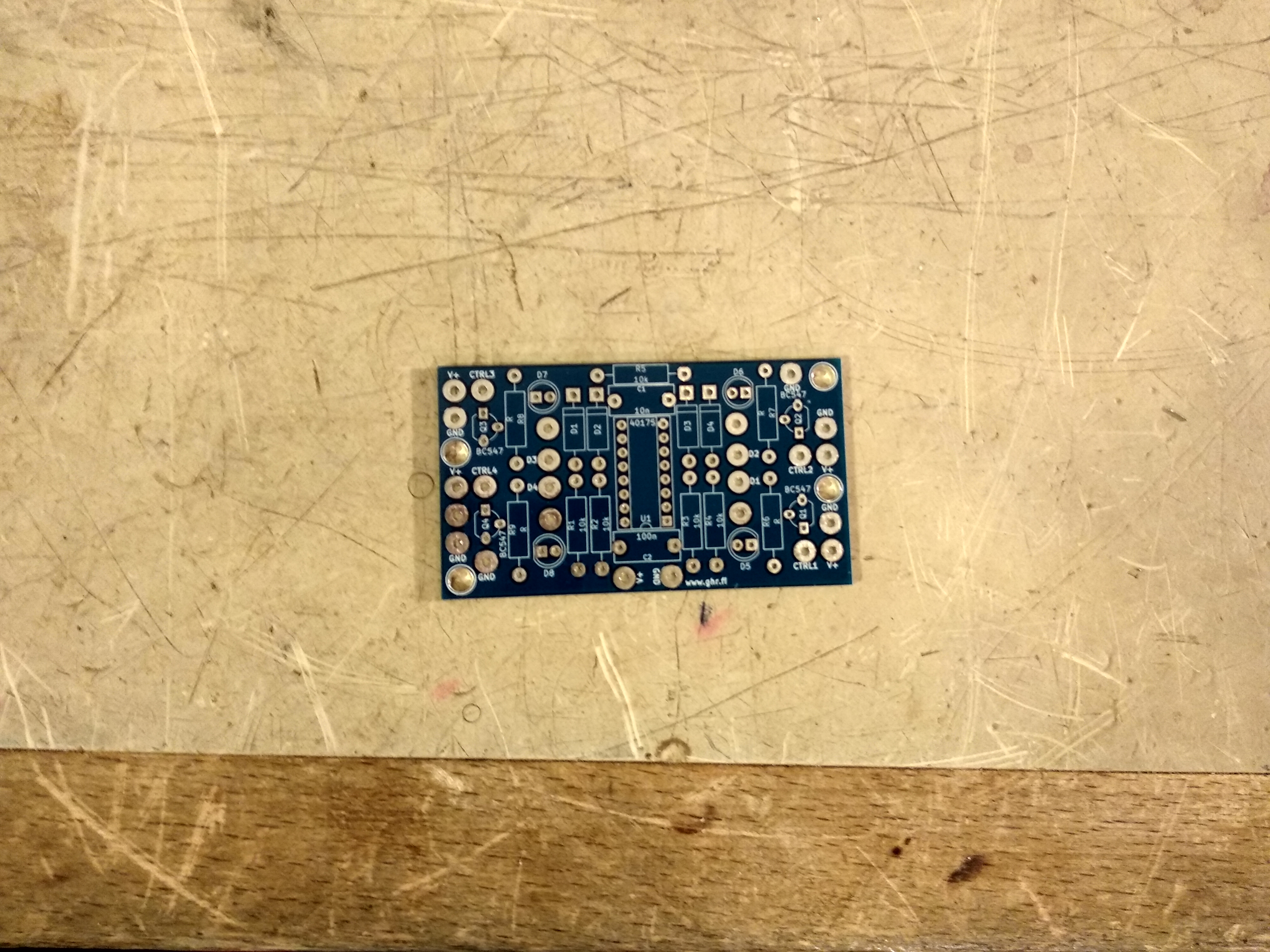
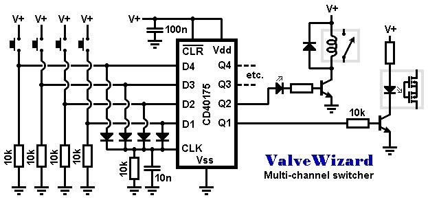
The gist of it is when a button is pressed a relay driver transistor turns on. Only one transistor will be on at a time.

You can find a description of how this kind of a circuit works here http://sound.whsites.net/project163.htm. Just scroll down to where it says Discrete CMOS Logic.
dorrisant wrote: Wed Sep 05, 2018 4:02 pm Nice work... but I don't know how excited I should be. Do you have a link for the circuit description from Merlin?
tristanc
Posts: 47
Joined: Fri Jun 15, 2018 3:33 pm

Re: Channel switcher PCB

Post by tristanc »

Very cool.
User avatar
V2
Posts: 124
Joined: Sun May 12, 2013 1:45 am
Location: Vancouver Canada

Re: Channel switcher PCB

Post by V2 »

What is V+ for this circuit?
Lauri
Posts: 70
Joined: Sun May 13, 2007 6:35 pm
Location: Finland

Re: Channel switcher PCB

Post by Lauri »

V2 wrote: Tue Dec 04, 2018 12:06 am What is V+ for this circuit?
Maximum recommended supply voltage for 40175 is 15V. V+ can be anything from 5V to 15V. Most likely you will want to use either 5V or 12V depending on what relays you're using.
User avatar
brejna
Posts: 57
Joined: Tue Aug 27, 2013 9:32 am
Location: Bosnia & Herzegovina

Re: Channel switcher PCB

Post by brejna »

Interesting project. Can individual switches be turned off, like pedal? So you have radio button option between 4 switches and option to bypass all?

Poslano sa mog Redmi Note 6 Pro koristeći Tapatalk

kdmay
Posts: 52
Joined: Mon Nov 01, 2010 11:26 am
Location: Melbourne, Australia

Re: Channel switcher PCB

Post by kdmay »

Great project!

I’ve had some of these made and in the next few weeks will incorporate into a 4 channel amp, so will report back.

Quick question: can 2 of these chips be used simultaneously for 8 channels? Wondering how the flip/flop reset would work in this instance

Cheers
User avatar
chief mushroom cloud
Posts: 420
Joined: Tue Jan 18, 2005 5:42 pm
Location: Peenemunde CA

Re: Channel switcher PCB

Post by chief mushroom cloud »

kdmay wrote: Mon Apr 29, 2019 1:00 am Quick question: can 2 of these chips be used simultaneously for 8 channels? Wondering how the flip/flop reset would work in this instance
Yes. We used this circuit for a set of amp monitoring and burn-in units in mfg....with two of these circuits per unit (8ch) and linked for a total of 24 ch...just connnect the CLK pins together.
Haven't tested more than that. Might need bi-directional buffer between CLK circuit sets if cable L get too long. We just use std midi cables to link clk and audio. Also used CD40xx buffers to drive relays...but I would use 2N7000 or similar to lo-side switch relays and LEDs for anything under 8ch. Also, DON'T share your relay logic gnd w/ your audio gnd.....reference terminate it at chassis common.
Don't overthink it. Just drink it.
User avatar
dorrisant
Posts: 2629
Joined: Tue Sep 21, 2010 1:27 pm
Location: Somewhere between a river and a cornfield
Contact:

Re: Channel switcher PCB

Post by dorrisant »

Very nice... I am a bit excited now, gotta try it out. Thank you very much for posting!
"Education is what you're left with after you have forgotten what you have learned" - Enzo
kdmay
Posts: 52
Joined: Mon Nov 01, 2010 11:26 am
Location: Melbourne, Australia

Re: Channel switcher PCB

Post by kdmay »

[quote="chief mushroom cloud" post_id=397727 time=1556724621 user_id=54]
[quote=kdmay post_id=397613 time=1556499639 user_id=9465]
Quick question: can 2 of these chips be used simultaneously for 8 channels? Wondering how the flip/flop reset would work in this instance
[/quote]
Yes. We used this circuit for a set of amp monitoring and burn-in units in mfg....with two of these circuits per unit (8ch) and linked for a total of 24 ch...just connnect the CLK pins together.
Haven't tested more than that. Might need bi-directional buffer between CLK circuit sets if cable L get too long. We just use std midi cables to link clk and audio. Also used CD40xx buffers to drive relays...but I would use 2N7000 or similar to lo-side switch relays and LEDs for anything under 8ch. Also, DON'T share your relay logic gnd w/ your audio gnd.....reference terminate it at chassis common.
[/quote]

Thanks mate

I am actually planning on building an 8 channel amp and 4 channel cab switcher, so this is helpful!

In the amp build I mentioned I am trialling this, I am definitely not going to share the logic ground with the audio ground. A buddy did this with one of the Tube Town Midi boards and had all sorts of troubles so had already warned me on this.
User avatar
dorrisant
Posts: 2629
Joined: Tue Sep 21, 2010 1:27 pm
Location: Somewhere between a river and a cornfield
Contact:

Re: Channel switcher PCB

Post by dorrisant »

Yes. No reason to ground it to the chassis.
"Education is what you're left with after you have forgotten what you have learned" - Enzo
azatplayer
Posts: 556
Joined: Thu Feb 26, 2009 7:59 pm
Location: Great Southland

Re: Channel switcher PCB

Post by azatplayer »

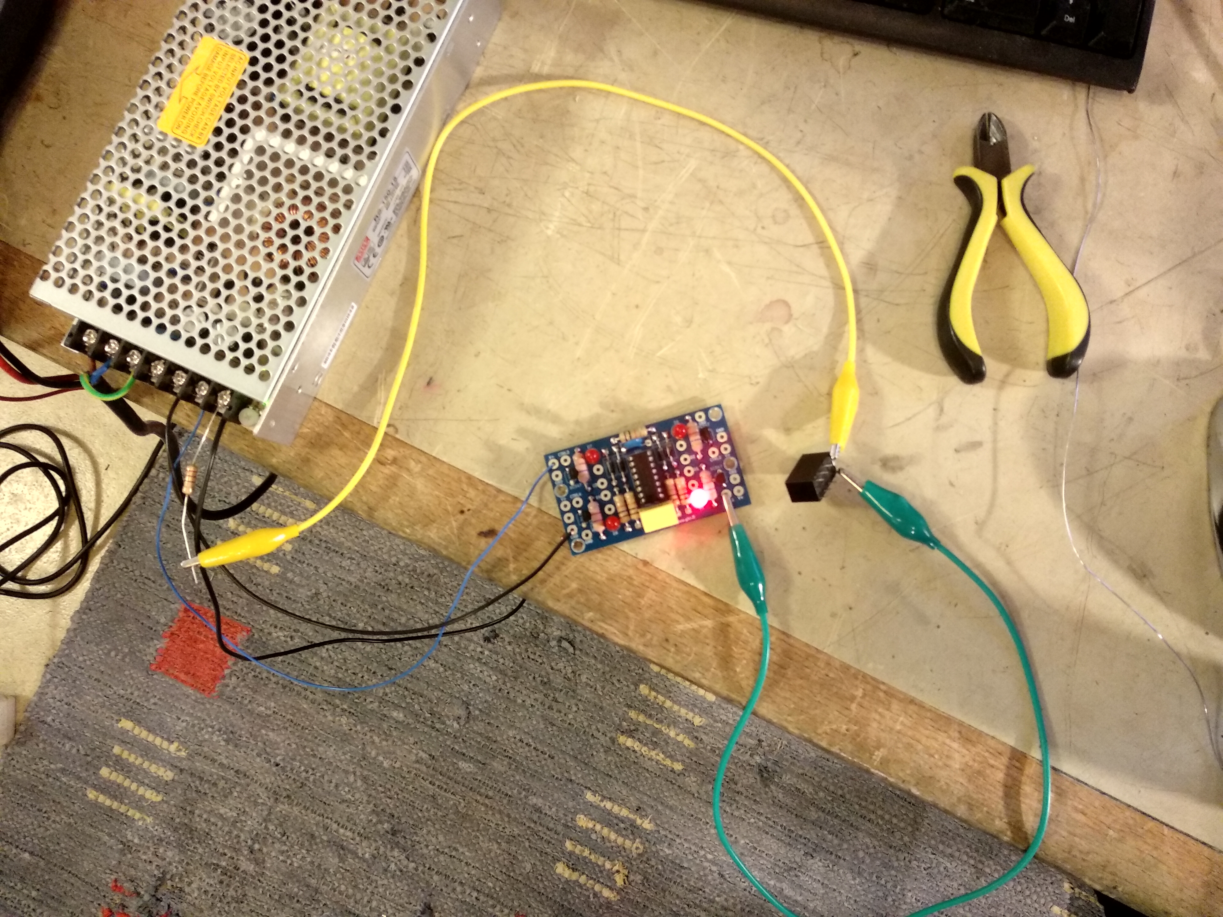
I’ve bread boarded this circuit and works well. However on power on, all switches are on.
Is this normal behaviour? Kinda not useful if it is!
I’m sure I’ve done a thing wrong 🤓
Post Reply