
FYI: those CE cables don't last for working musicians. They are just not hardy. I went through a couple with internal breaks, then put MIDI jacks on the footswitch and amp. I now use a standard heavy duty MIDI cable.
Your mileage may vary.
All disclaimers apply
Check with your dealer for details
.........
D
Cable for Footswitch: NOW FIXED, added PICS
Moderators: pompeiisneaks, Colossal
Re: Cable for Footswitch: NOW FIXED, added PICS
There are no stupid questions, just stupid people.......

Re: Cable for Footswitch: NOW FIXED, added PICS
+1 that's exactly what I do!dobbhill wrote:FYI: those CE cables don't last for working musicians. They are just not hardy. I went through a couple with internal breaks, then put MIDI jacks on the footswitch and amp. I now use a standard heavy duty MIDI cable.
Your mileage may vary.
All disclaimers apply
Check with your dealer for details
.........
D
"Let's face it, the non HRMs are easier to play, there, I've said it." - Gil Ayan... AND HE"S IN GOOD COMPANY!
Black chassis' availble: http://cepedals.com/Dumble-Style-Chassis.html
Black chassis' availble: http://cepedals.com/Dumble-Style-Chassis.html

Re: Cable for Footswitch: NOW FIXED, added PICS
I have the CE 3 button footswitch with the 4 conductor cable.
I didn't want to use it though as it looked weak and also only had 4 conductors in the cable.
I ended up buying a MIDI cable yesterday and used two jacks I had at home. All is good now!
Just need to find a multi colour 3mm common anode LED for my footswitch now....
I didn't want to use it though as it looked weak and also only had 4 conductors in the cable.
I ended up buying a MIDI cable yesterday and used two jacks I had at home. All is good now!
Just need to find a multi colour 3mm common anode LED for my footswitch now....
-
martin manning

- Posts: 13327
- Joined: Sun Jul 06, 2008 12:43 am
- Location: 39°06' N 84°30' W
Re: Cable for Footswitch: NOW FIXED, added PICS
Only 4 conductors in this cable too, as I recall. The box is alright, switches are maybe not the best but serviceable.tubedogsmith wrote:The 3 switch footswitches at CE Distribution(Antique Electronics) have the cords and 5 pin plugs that fit those jacks. The boxes are resonably priced as well. 5 pins and the switches and LEDs in side are easy to rewire.
Re: Cable for Footswitch: NOW FIXED, added PICS
I use the AES three button with led as well.
I didn't try to make the stock cable and plug work.
I changed the mid boost led to yellow, OD stayed red and the PAB to green.
Switches aren't top quality but so far so good.
I didn't try to make the stock cable and plug work.
I changed the mid boost led to yellow, OD stayed red and the PAB to green.
Switches aren't top quality but so far so good.
Tom
Don't let that smoke out!
Don't let that smoke out!
-
tubedogsmith
- Posts: 597
- Joined: Mon Jan 17, 2005 11:52 pm
Re: Cable for Footswitch: NOW FIXED, added PICS
we must be talking about something different or something changed. The ones I got several years ago had 5 wires and were as robust as anything else out there, both 2 button and 3 button pedals.
Re: Cable for Footswitch: NOW FIXED, added PICS
All I'm using is the enclosure and LED holders.Structo wrote:I use the AES three button with led as well.
I didn't try to make the stock cable and plug work.
I changed the mid boost led to yellow, OD stayed red and the PAB to green.
Switches aren't top quality but so far so good.
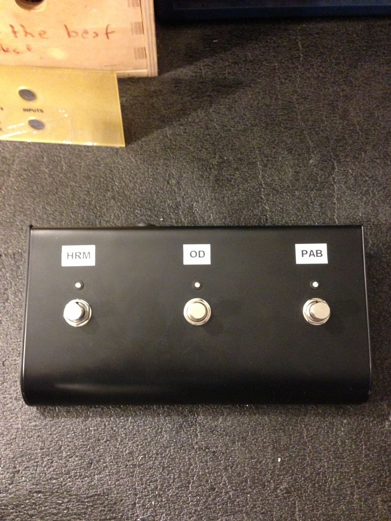
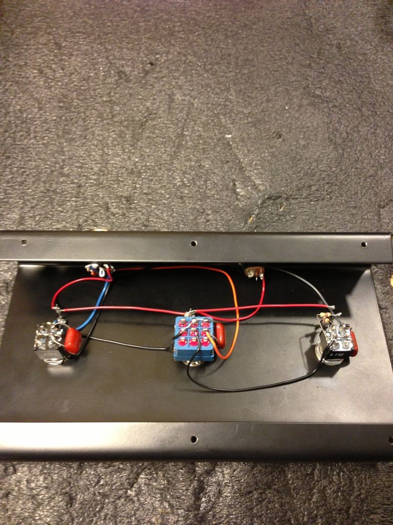
Added a 5 pin DIN jack for a MIDI cable, added a DC jack so I can power pedals using the footswitch then replaced all three switches (2 DPDT and 1 3PDT).
Footswitch controls OD, PAB and Fender/Marshall HRM TS.
Re: Cable for Footswitch: NOW FIXED, added PICS
Here is the final footswitch
[IMG:768:1024]http://img.photobucket.com/albums/v610/ ... E7DB0B.jpg[/img]
[IMG:768:1024]http://img.photobucket.com/albums/v610/ ... 930BD9.jpg[/img]
HRM LED only comes on when the OD is activiated. HRM has a bi-colour LED. Red LED is Fender HRM tonestack and Green LED is Marshall HRM tonestack.
DC power jack supplies DC voltage to run pedals. No carrying extra power supplies.
-
bluesfendermanblues
- Posts: 1314
- Joined: Tue May 22, 2007 12:57 pm
- Location: Dumble City, Europe
Re: Cable for Footswitch: NOW FIXED, added PICS
Hi Chris, Neat feature having a Marshall/Fender HRM circuit - Are you simply changing the slope resistor on the HRM board??ChrisM wrote:Here is the final footswitch
[IMG:768:1024]http://img.photobucket.com/albums/v610/ ... E7DB0B.jpg[/img]
[IMG:768:1024]http://img.photobucket.com/albums/v610/ ... 930BD9.jpg[/img]
HRM LED only comes on when the OD is activiated. HRM has a bi-colour LED. Red LED is Fender HRM tonestack and Green LED is Marshall HRM tonestack.
DC power jack supplies DC voltage to run pedals. No carrying extra power supplies.
Diva or not? - Respect for Mr. D's work....)
Re: Cable for Footswitch: NOW FIXED, added PICS
Chris I would be interested in how you did the 9vdc supply to the pedal.
That is a great idea.
That is a great idea.
Tom
Don't let that smoke out!
Don't let that smoke out!
Re: Cable for Footswitch: NOW FIXED, added PICS
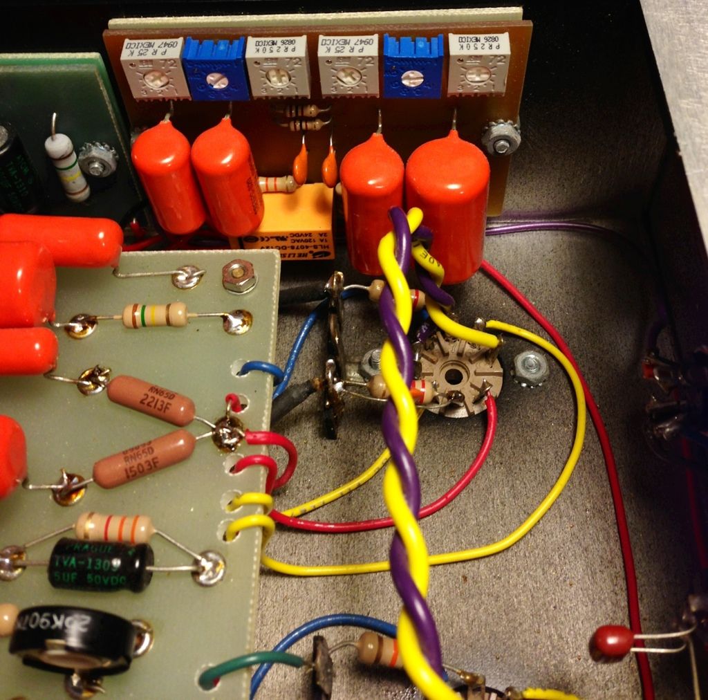
Two separate tone stacks. One Fender and one Marshall, each has their own trimmers. This way I can really dial in two unique overdrive tones.
Here is the tone stack board with the 12V relay. You can see it is mounted right by the foot switch and also close to where the HRM board originally would go.
[IMG 1012]http://img.photobucket.com/albums/v610/ ... 69D42E.jpg[/img]
Tom,
The footswitch has a +12V connection and a ground connection. Simply hook these up to a DC jack and your set. The aux 12V transformer in the amp has more than enough current to run a bunch of pedals.
Here is the tone stack board with the 12V relay. You can see it is mounted right by the foot switch and also close to where the HRM board originally would go.
[IMG
 1012]http://img.photobucket.com/albums/v610/ ... 69D42E.jpg[/img]
Tom,
The footswitch has a +12V connection and a ground connection. Simply hook these up to a DC jack and your set. The aux 12V transformer in the amp has more than enough current to run a bunch of pedals.
-
bluesfendermanblues
- Posts: 1314
- Joined: Tue May 22, 2007 12:57 pm
- Location: Dumble City, Europe
Re: Cable for Footswitch: NOW FIXED, added PICS
Very nice Chris - clean looking build!
Have yopu tried running the anode and cathode wires on V1 a little closer - gives a tiny little bit more bloom to the tone IME.
Have yopu tried running the anode and cathode wires on V1 a little closer - gives a tiny little bit more bloom to the tone IME.
Diva or not? - Respect for Mr. D's work....)
Re: Cable for Footswitch: NOW FIXED, added PICS
That is a very cool idea.ChrisM wrote:
Tom,
The footswitch has a +12V connection and a ground connection. Simply hook these up to a DC jack and your set. The aux 12V transformer in the amp has more than enough current to run a bunch of pedals.
So you are running 12vdc to your 9v pedals, no problem?
I was thinking you would need a 9v regulator plus more filtering?
Tom
Don't let that smoke out!
Don't let that smoke out!
Re: Cable for Footswitch: NOW FIXED, added PICS
12V is fine for pedals. Not going to fry anything. Get a little more headroom with 12V over 9V.Structo wrote:That is a very cool idea.ChrisM wrote:
Tom,
The footswitch has a +12V connection and a ground connection. Simply hook these up to a DC jack and your set. The aux 12V transformer in the amp has more than enough current to run a bunch of pedals.
So you are running 12vdc to your 9v pedals, no problem?
I was thinking you would need a 9v regulator plus more filtering?
You could always add a 9V regulator (plus filtering) in the footswitch if you wanted.

Re: Cable for Footswitch: NOW FIXED, added PICS
Why not use a 7809 and 9V relays? That way you have a 9V supply. I would fuse the 9VDC effects pedal supply in the footswitch. Replacing parts in the amp is a pain.
Chris, nice looking build!
Have fun, Jelle
Chris, nice looking build!
Have fun, Jelle
ChrisM wrote:12V is fine for pedals. Not going to fry anything. Get a little more headroom with 12V over 9V.Structo wrote:That is a very cool idea.ChrisM wrote:
Tom,
The footswitch has a +12V connection and a ground connection. Simply hook these up to a DC jack and your set. The aux 12V transformer in the amp has more than enough current to run a bunch of pedals.
So you are running 12vdc to your 9v pedals, no problem?
I was thinking you would need a 9v regulator plus more filtering?
You could always add a 9V regulator (plus filtering) in the footswitch if you wanted.