
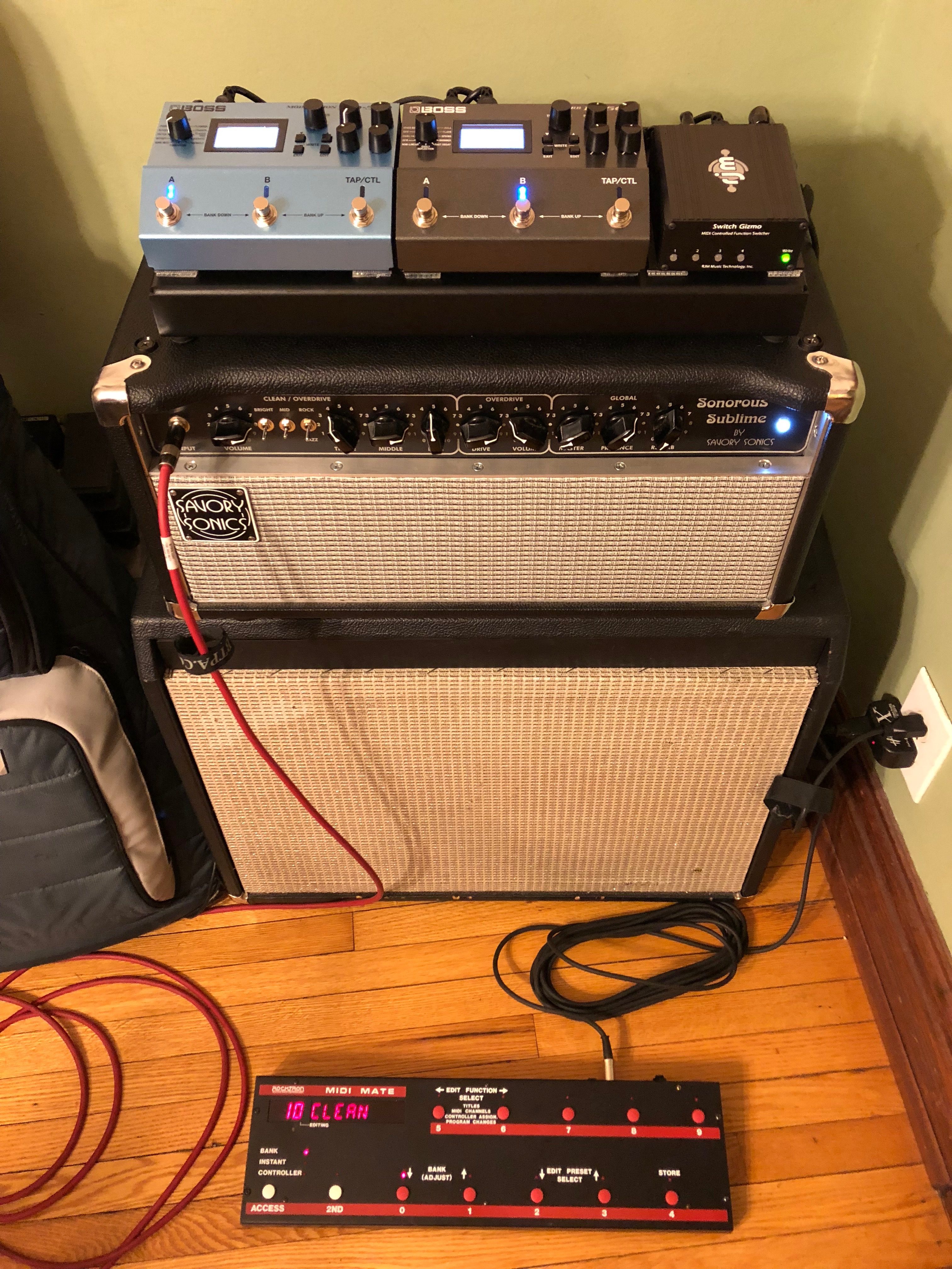
Back in the day, I played with my FX housed in a rack located along with my D-lator clone underneath the amp head. The cable length between the D-lator and FX was maybe about 1-2 ft, such that loss of highs at that particular junction was neither a concern nor a consideration. Setting the Dumbleator was just a matter of turning knobs to where things sounded best to me, not too big of a balancing act. At some point, for the sake of simplicity, I moved towards using a pedalboard and either backline equipment or my amps as a clean platform. Made gigs a lot easier, and I stayed that way for years. Recently, however, I started toying with the idea of using my amp's overdrive again while keeping the pedalboard. My pedalboards are "splitable," where time-based FX can go in the amp's loop and the rest of the stuff up front, allowing use of the amp's overdrive again. This now meant that the D-lator clone would be underneath the amp head like before, but now it would connect to the pedalboard via an 18 ft cable. This opened Pandora's box.
First I wondered whether I would more easily overdrive my FX than before if the D-lator send was too hot for instrument level, pedal FX. While my rackmount FX are line level and have LEDs indicating signal levels, my pedals (TC) don't. However, I found out the TC stuff I use has a lot of headroom for a pedal running off a 9 VDC supply, and the pedals will not clip even when fed line level signals. What complicated things, though, is that sometimes things sounded fine, but others the sound was muffled. A little math went a long ways here. My D-lator clone has 250K pots, and if the Send control is at half of the pots value, the output impedance of the Send port will be basically 125//125 = 62.5K. If the capacitance of the cable is say 40 pF/ft, for an 18 ft long cable the total capacitance is 720 pF. The 3 dB frequency for the low pass filter formed by the Send output impedance and the cable's capacitance is f = 1/(2* Pi()*R*C) = 3.5 KHz, which explains the muffled sound. Now, if the Send pot is now dialed at 10% (or 90%) instead, the output impedance is now 22.5 KHz. While somewhat high, this shifts the 3 dB frequency point to almost 9 KHz. Or, if the pot is dialed all the way up, the output impedance is determined by the cathode follower only and becomes about 600 ohms, shifting the 3 dB frequency point to over 330 KHz.
I thought about replacing the Send pot with a lower value one, maybe 10 or 25K, but I didn't have any around. The more I played with the settings, the more I discovered there is a lot of room either brighten up or tame down the sound without even starting to mess with the D-lator bright caps. I actually kind of like this, so for now the D-lator clone is staying as is. With the help of a snake I put together for the pedalboard, which makes set up and tear down pretty manageable, I'm pretty excited about using all of the amp's sounds again. First gig went great, the dynamic range of the amp is definitely broader than the pedals, and I think I missed that.
Gil
PS: More About Dumbleator Settings
Moderators: pompeiisneaks, Colossal
-
norburybrook

- Posts: 3290
- Joined: Mon Jan 06, 2014 12:47 am
- Location: London
- Contact:
Re: PS: More About Dumbleator Settings
Gill,
I have a similar set up, split pedal board with in front FX and a loop. The way I got round any long cable losses was simple; I put peter Cornish Buffers on my in/out to the FX loop. I have a break out box and the buffers are in there along with a non buffer chain if wanted. This meant zero tone change from FX to and from the amp loop.
M
Re: PS: More About Dumbleator Settings
I'm unclear as to what you meant by "...Buffers on my in/out to the FX loop." What FX loop are you referring to? The amp's "Preamp Out" "Power Amp In," the D-lator's "Send" and "Return," or your pedalboard's interface box? Suspect the latter, but would like to be sure before I write my response.norburybrook wrote: ↑Fri Jun 28, 2019 6:52 pm Gill,
I have a similar set up, split pedal board with in front FX and a loop. The way I got round any long cable losses was simple; I put peter Cornish Buffers on my in/out to the FX loop. I have a break out box and the buffers are in there along with a non buffer chain if wanted. This meant zero tone change from FX to and from the amp loop.
M
Cheers,
G.

Re: PS: More About Dumbleator Settings
My way around the loop cable tone loss is to put my pedals (Boss MD-500 and RV-500) on top of the amp and control them via MIDI. I had previously tried a Klon style buffer running at 24volts (to avoid clipping the buffer) after the D-Lator send, but found that it altered the tone in a way that I didn't like. I found that there was just too much tone loss when running long cables to the board out front. Even now, with the short cables, running the send much beyond half dulls the amp out too much for my taste.
-Aaron
-Aaron
Re: PS: More About Dumbleator Settings
Gil
Here is where I have gone.
It is an in-phase Serial/Parallel mix control right on the Lator. Turn the mix all the way to the right and it's serial, CCW it's a dry amp. This way I am not sending everything through those long ass runs just enough to get swamped with reverb and a little delay that gets fed back in at the mixer. I am also not asking for as much headroom from my pedals since the send control is only being used to send just the wet signal. This also makes tweaking throughout the night a breeze if you want more effects or if you have an issue with cables or your board the only thing you will lose is your effects and not the whole rig (Just flip the mixer to "dry" setting). The only thing I notice is a Parallel set-up has a different feel and response than the serial one does?. Like it or hate it you get used to it over time. Somewhere I have a schematic for it your interested I dig it out and post it.
BTW. Are you happy with that setup or are you still experimenting with it?
IMO it's kind of strange that in OD mode (with the serial Loop) you have a pot (OD volume) feeding a pot (Master) then a buffer feeding another pot (send) before you even get to the effx. That's allot of voltage dividers
Tony
Last edited by talbany on Sat Jun 29, 2019 4:08 am, edited 3 times in total.
" The psychics on my bench is the same as Dumble'"
Re: PS: More About Dumbleator Settings
Hey Tony! You can shoot me a schematic, if you can easily find it. Am I happy? I'm enthused about using the amp's OD again, but happy (as far as tone goes) is a strong word. Pedals make life easy, but the amp can sound better when the planets line up.talbany wrote: ↑Sat Jun 29, 2019 3:48 am Gil
Here is where I have gone.
It is an in-phase Serial/Parallel mix control right on the Lator. Turn the mix all the way to the right and it's serial, CCW it's a dry amp. This way I am not sending everything through those long ass runs just enough to get swamped with reverb and a little delay that gets fed back in at the mixer. I am also not asking for as much headroom from my pedals since the send control is only being used to send just the wet signal. This also makes tweaking throughout the night a breeze if you want more effects or if you have an issue with cables or your board the only thing you will lose is your effects and not the whole rig. The only thing I notice is a Parallel set-up has a different feel and response than the serial one does?. Like it or hate it you get used to it over time. Somewhere I have a schematic for it your interested I dig it out and post it.
BTW. Are you happy with that setup or are you still experimenting with it?
IMO it's kind of strange that in OD mode (with the Lator) you have a pot (OD volume) feeding a pot (Master) then a buffer feeding another pot (send) before you even get to the effx. That's allot of voltage dividers
Tony
G.
Re: PS: More About Dumbleator Settings
Yeah I know I still go back and forth as well between pedals and ampHey Tony! You can shoot me a schematic, if you can easily find it. Am I happy? I'm enthused about using the amp's OD again, but happy (as far as tone goes) is a strong word. Pedals make life easy, but the amp can sound better when the planets line up.
G.
Tony
" The psychics on my bench is the same as Dumble'"
Re: PS: More About Dumbleator Settings
Thanks, Tony!
-
norburybrook
- Posts: 3290
- Joined: Mon Jan 06, 2014 12:47 am
- Location: London
- Contact:
Re: PS: More About Dumbleator Settings
Gill,ayan wrote: ↑Fri Jun 28, 2019 8:22 pmI'm unclear as to what you meant by "...Buffers on my in/out to the FX loop." What FX loop are you referring to? The amp's "Preamp Out" "Power Amp In," the D-lator's "Send" and "Return," or your pedalboard's interface box? Suspect the latter, but would like to be sure before I write my response.norburybrook wrote: ↑Fri Jun 28, 2019 6:52 pm Gill,
I have a similar set up, split pedal board with in front FX and a loop. The way I got round any long cable losses was simple; I put peter Cornish Buffers on my in/out to the FX loop. I have a break out box and the buffers are in there along with a non buffer chain if wanted. This meant zero tone change from FX to and from the amp loop.
M
Cheers,
G.
the signal going to and from the Dumbleator goes through a buffered IO breakout box on my pedal board. So there's no tone loss with long cables at all.
the Volume pedal, Freeze, Zendrive and POG go straight in front of the amp the rest are in the FX loop. It's what's known as the 4 cable method as I'm sure you know
You do not have the required permissions to view the files attached to this post.

Re: PS: More About Dumbleator Settings
Gil: can you explain on the output impedance of the cathode follower?
In your calculations you did not take account for the tube impedance?
In my understanding you take these also in account?
I messed a lot with Dlators. I built 4 external and 2 internal of them with different capacitors, different cathode resistors and settled with the "old style" 10k/1k5 cathode style. This one has more compression and a bit darker compared to the 27k/1k8 one.
Flipping the 270pF on the recovery does it for me.
That way I can put a really hot signal on the cathode follower and keep the drive pot half way without becoming too dark.
Ps. I use RG400 cable. In your case its capacitance would be 475pF for 18ft.
Re: PS: More About Dumbleator Settings
Understood, I think. The thing is, having the buffer on the board should not affect any signal loss between the Dumbleator SEND jack and where it connects to on the board. Losses are prevented downwind by a buffer because its low output impedance, but not upwind. It's like when we have a buffer at the input of a pedalboard and we plugg a guitar into it. If there is a volume pedal after the buffer, it will not lose highs when turned down. However, the volume pot on the guitar will still lose highs when turned down, and the longer the cable, the more so. What is the value of your Dumbleator SEND pot? If it's the stock 250 K, I suspect you will find a difference in treble response between when set all the way up versus halfway (value-wise) up.norburybrook wrote: ↑Sat Jun 29, 2019 9:05 am Gill,
the signal going to and from the Dumbleator goes through a buffered IO breakout box on my pedal board. So there's no tone loss with long cables at all.
the Volume pedal, Freeze, Zendrive and POG go straight in front of the amp the rest are in the FX loop. It's what's known as the 4 cable method as I'm sure you know
M
Gil
Re: PS: More About Dumbleator Settings
Sure, it's an approximation which I'll go through below. The output impedance of the Dumbleator's 12AX7 cathode follower is about 600 ohms. The 250 K SEND pot is in series with that. What I said was:erwin_ve wrote: ↑Sat Jun 29, 2019 10:21 am Gil: can you explain on the output impedance of the cathode follower?
In your calculations you did not take account for the tube impedance?
In my understanding you take these also in account?
I messed a lot with Dlators. I built 4 external and 2 internal of them with different capacitors, different cathode resistors and settled with the "old style" 10k/1k5 cathode style. This one has more compression and a bit darker compared to the 27k/1k8 one.
Flipping the 270pF on the recovery does it for me.
That way I can put a really hot signal on the cathode follower and keep the drive pot half way without becoming too dark.
Ps. I use RG400 cable. In your case its capacitance would be 475pF for 18ft.
"A little math went a long ways here. My D-lator clone has 250K pots, and if the Send control is at half of the pots value, the output impedance of the Send port will be basically 125//125 = 62.5K."
In reality, from the wiper of the 250 K pot, one side will see 125 K to ground, and the other side will 125 K + 0.6 K to ground. Their parallel is 62.6 K, instead of 62.5 K. So the output impedance of the SEND port is 62.6 K.
Along similar lines, I said when the SEND pot is all the way up, the output impedance of the SEND jack would be about 600 ohms, which accounts for the cathode follower alone. In reality, that 600 ohms is in parallel with the 250 K pot and the output impedance at the SEND port is 599 Ohms.
Gil
-
martin manning

- Posts: 13279
- Joined: Sun Jul 06, 2008 12:43 am
- Location: 39°06' N 84°30' W
Re: PS: More About Dumbleator Settings
Marcus you would have to arrange your cables and buffers like this to reduce cable losses.
You do not have the required permissions to view the files attached to this post.
Last edited by martin manning on Sat Jun 29, 2019 5:09 pm, edited 1 time in total.
Re: PS: More About Dumbleator Settings
Hi Martin!martin manning wrote: ↑Sat Jun 29, 2019 4:45 pm Marcus you would have to arrange your cables and buffers like this to reduce cable losses.
-
martin manning
- Posts: 13279
- Joined: Sun Jul 06, 2008 12:43 am
- Location: 39°06' N 84°30' W
Re: PS: More About Dumbleator Settings
Yes, and very well explained, too. I just thought I'd take the last step and diagram it.