I'm going to want 6V relays, since I'm planning to use the 5V supply from my PT. Also - would you recommend a zener-based circuit to control the relay power? Can you recommend a circuit? (This is my first foray into footswitching on an amp I build.)
And and all advice welcome.
Preferred relays? Relay power circuit?
Moderators: pompeiisneaks, Colossal
Re: Preferred relays? Relay power circuit?
If you go with pedal leds in series with the relay coil I suggest to choose 5V relays because the leds eat 1.7 volts.
Stabilized supply (zener) is not necessary.
Teo
Stabilized supply (zener) is not necessary.
Teo
-
Funkalicousgroove

- Posts: 2232
- Joined: Mon Jul 25, 2005 8:04 pm
- Location: Denver, CO
- Contact:
Re: Preferred relays? Relay power circuit?
NTE General purpose relays work just fine, I usually rectify a 6.3v trannie Full wave bridge, into a 1000uf cap, then a 5V regulator, then another 1000uf cap. I use the 5/6v relays.
Owner/Solder Jockey Bludotone Amp Works
Re: Preferred relays? Relay power circuit?
www.hoffmanamps.com has a good duide to knocking up a relay supply board.
I did the full wave bridge rectifier and smoothing caps from the heater supply and it works great on my build.
cheers
Pete
I did the full wave bridge rectifier and smoothing caps from the heater supply and it works great on my build.
cheers
Pete
Re: Preferred relays? Relay power circuit?
The WeberVST Twin transformer has a separate 12V 1A tap that works well for powering a relay.

Re: Preferred relays? Relay power circuit?
Weber also has channel-switching boards for sale. They run off the 6V supply.
-
Funkalicousgroove
- Posts: 2232
- Joined: Mon Jul 25, 2005 8:04 pm
- Location: Denver, CO
- Contact:
Re: Preferred relays? Relay power circuit?
those are great, but they're quite big, I have a couple I'd part with in exchange for some 6ps orange drops if anyone is interested.
Owner/Solder Jockey Bludotone Amp Works
Re: Preferred relays? Relay power circuit?
Do we want Latching or non-latching relays? (whats the diff?)
Re: Preferred relays? Relay power circuit?
We want non-latching relays. Latching relays switch and stay until you apply a voltage to the opposite side. Non-latching stay switched as long as power is applied, then switch back when voltage is removed.Bennypapa wrote:Do we want Latching or non-latching relays? (whats the diff?)
Re: Preferred relays? Relay power circuit?
I built a relay board yesterday. I used the heater voltage into a bridge, I had 2 220uF 25V electrolytics so I used them with a 150 ohm resistor between them for filtering, then into a 6V 1A relay with a 4007 diode across it. I left the ground from the relay coil open so to switch you just ground the coil.
I'll draw a schematic later, this was all scribbled down.
It seems to work fine. When I put it in the amp I'll put a switching jack in the amp, connect the hot side of the coil to the non-switched side, and the front panel switch to the switched side. This way the panel switch will be de-activated when the footswitch is in.
My next task is to add LED's to the front panel.
Re: Preferred relays? Relay power circuit?
Bob-I
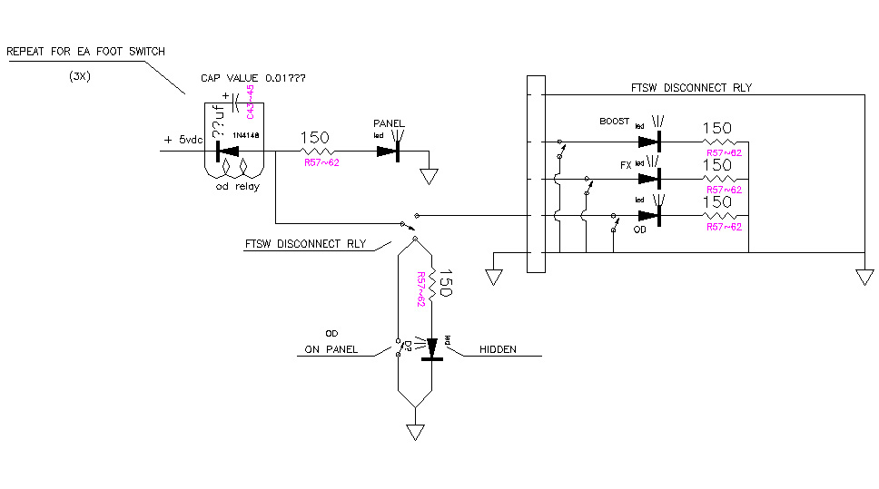
I have just the thing for you. I have had a lot of help from folks in designing a footswitching scheem to allow for boost, overdrive, and fx loop switching at the pedal with leds at the pedal and on the panel. It also allows for switches on the panel. With the plug in, the panel switches are inactive and vice versa.
Take a look at the attached and remember that it is designed with 5vdc, dpdt relays. When the led is grounded it lights and the relay coil is de-energized, switching the circuit.
Bennypapa
cant get it to attach
look at
http://web.qx.net/bennypapa/electronics/ftsw.jpg
see if that looks like it will work.
Its late, goodnight.
Re: Preferred relays? Relay power circuit?
Thx. I'll take a look at it later. Like you said... it's late.Bennypapa wrote:Bob-I
I have just the thing for you. I have had a lot of help from folks in designing a footswitching scheem to allow for boost, overdrive, and fx loop switching at the pedal with leds at the pedal and on the panel. It also allows for switches on the panel. With the plug in, the panel switches are inactive and vice versa.
Take a look at the attached and remember that it is designed with 5vdc, dpdt relays. When the led is grounded it lights and the relay coil is de-energized, switching the circuit.
Bennypapa
cant get it to attach
look at
http://web.qx.net/bennypapa/electronics/ftsw.jpg
see if that looks like it will work.
Its late, goodnight.
Re: Preferred relays? Relay power circuit?
I just looked at that again and it is crap!!!!
Ignore it and I'll repost when I have a chance to redraw it.
CRAP! I thought I had it figured out.
Bennypapa
Ignore it and I'll repost when I have a chance to redraw it.
CRAP! I thought I had it figured out.
Bennypapa
Re: Preferred relays? Relay power circuit?
Try that same url again. I changed the dwg.
Re: Preferred relays? Relay power circuit?
Bob, sounds like you have it down already.
sounds very similar to the f/switch at hoffman amps page.
I followed that, and mounted bright blue LED for clean so that the "OFF" position is OD and blue LED shows me the CL setting.
I like it - for me CL is less often so is the "activated" channel.
cheers
Pete C
sounds very similar to the f/switch at hoffman amps page.
I followed that, and mounted bright blue LED for clean so that the "OFF" position is OD and blue LED shows me the CL setting.
I like it - for me CL is less often so is the "activated" channel.
cheers
Pete C