GZ34S vs 5U4GB --- voltage drop question, plus a discussion of SS diodes as backup

General discussion area for tube amps.

Moderators: pompeiisneaks, Colossal

User avatar
xtian
Posts: 7022
Joined: Mon Apr 19, 2010 8:15 pm
Location: NorCal
Contact:

GZ34S vs 5U4GB --- voltage drop question, plus a discussion of SS diodes as backup

Post by xtian »

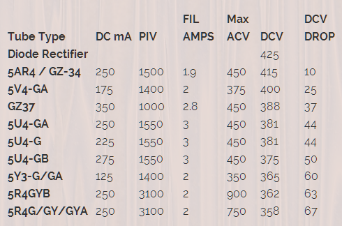
See chart below. GZ34 drops about 10v under load, and 5U4GB drops about 50v.

In my new Deluxe Reverb build, I was using a JJ GZ34S. 6V6 plates at 460v, and bias about 15mA each tube.

I thought I'd try a 5U4GB to lower the plate voltage, but after setting the bias to 16mA, the plate voltage is 440v. Why only a 20v change?

Image
Last edited by xtian on Sun Dec 11, 2022 5:56 pm, edited 1 time in total.
I build and repair tube amps. http://amps.monkeymatic.com
sluckey
Posts: 3103
Joined: Sun Jul 22, 2007 7:48 pm
Location: Mobile, AL
Contact:

Re: GZ34S vs 5U4GB --- voltage drop question

Post by sluckey »

That chart is great for showing the relative voltage drop for different rectifier tubes. But the drop across a rectifier tube is not a fixed voltage. The drop is very dependent on the amount of current demand. Lighter current means less drop. Higher currents means more drop.
User avatar
xtian
Posts: 7022
Joined: Mon Apr 19, 2010 8:15 pm
Location: NorCal
Contact:

Re: GZ34S vs 5U4GB --- voltage drop question

Post by xtian »

So the DROP* column should be *at max rated current? Makes sense.
I build and repair tube amps. http://amps.monkeymatic.com
User avatar
trobbins
Posts: 198
Joined: Tue Jun 01, 2010 8:51 am
Location: Australia

Re: GZ34S vs 5U4GB --- voltage drop question

Post by trobbins »

xtian wrote: Sat Dec 10, 2022 4:39 am So the DROP* column should be *at max rated current? Makes sense.
It's a bit too simple to even state a condition like 'max rated current', especially for the ubiquitous capacitor input filter rectifying circuit - where the current through the diode is most like a half-sine shape (ie. its average and peak values are quite different). And what makes it harder to comprehend is that the DC load current drawn from B+ by the amplifier circuitry is not the same current value as either the diode peak current or the diode average current.

So that table is more an indicator of whether changing a diode will likely increase or decrease the B+ level. For a particular amp, it may be better to google for some forum posts where someone has measured the change they observed.

Googling may also help to highlight the other risks and issues that arise from swapping a GZ34 to a 5U4G, even for a quick trial - such as stressing filter and coupling cap max/surge voltage ratings.
User avatar
Littlewyan
Posts: 1917
Joined: Thu Sep 12, 2013 6:50 pm
Location: UK

Re: GZ34S vs 5U4GB --- voltage drop question

Post by Littlewyan »

What 6V6s are you using? If they're 14W versions then bring the idle current up and a bit and the voltage should drop. I would start at 60% idle dissipation in a Deluxe Reverb, so bring it up to 19mA.
User avatar
LOUDthud
Posts: 352
Joined: Tue Sep 25, 2007 9:27 pm
Location: Texas

Re: GZ34S vs 5U4GB --- voltage drop question

Post by LOUDthud »

The problem with most of these charts is that there are too many unknowns. Were the tubes all tested with the same filter capacitance ? In fact, in this case, was the 20V drop just the drop at idle, or full blast overdrive ? Attached is a chart I got on another website, I've tried to point out which curve is which tube, the colors are too close together for my old eyes. Again the chart just shows instantaneous Voltage drop, not what you will see on the filter cap.
figure01_ed.JPG
You do not have the required permissions to view the files attached to this post.
R.G.
Posts: 1243
Joined: Tue Dec 02, 2014 9:01 pm

Re: GZ34S vs 5U4GB --- voltage drop question

Post by R.G. »

+1 to what L.T., trobbins, and others said.
DC voltage out of a first filter cap, ripple voltage, and diode currents are mildly complicated in a diode-capacitor power supply.

The diode does not conduct at all until the voltage across it is in the correct direction. So if the filter cap has a voltage on it, the diode current is >zero< until the AC voltage driving it is higher than the capacitor voltage. Once this happens, the current in the diode rises until it fills the capacitor as much as its internal resistance will let it, but as the AC voltage driving the diode drops again, eventually it gets below the capacitor voltage and current in the diode drops to zero again for the rest of the half-sine wave.

This results in the classical form of a sawtooth ripple voltage - a sharp rise in voltage on the filter cap, followed by a longer and slower taper down as the capacitor supplies the load by itself. The ripple voltage decline down continues until the AC line polarity changes and rises again to turn the diode on.

For a diode + capacitor filter, all of the power that eventually goes out to the load has to go into the capacitor in a short portion of the AC sine wave near the peak of the AC wave. So the diode current has to be higher than the DC load current. For solid state diodes, with their low forward voltage and low resistance, the current pulses are short and sharp. The pulse peaks may be several times the DC load. Since the value of the filter cap determines how far down the ripple current sags at a given load, the bigger the capacitor value, the shorter and sharper the diode current peaks get.

Tube rectifiers have a much higher internal resistance than solid state, so they turn on and off more slowly, and let a higher percentage of the AC sine wave through into the cap, but this comes at the cost of bigger internal losses (they get HOT) and bigger ripple voltages.

Since the rectifier current peaks (and hence voltage drop) vary with current, how far the capacitor sags before it gets another pulse from the rectifiers depends on the capacitance value and the load current for any given rectifier. It's not accurate to say how much the DC voltage in a tube rectified power supply varies with different tubes without specifying the conditions they're tested at. A GZ34-ish tube has an internal resistance of approximately ... um, 50 ohms if I remember correctly, and a 5U4-ish is about 150 ohms. So in the same conditions, the GZ would produce a higher DC voltage.How much higher depends on the load.

This also points up a fairly easy dodge - fake the rectifier tube with solid state diodes and a power resistor. Using a power resistor to model the internal resistance of a rectifier tube as well as > changing < the resistance to "fake" a different rectifier tube. This can be quite an accurate reproduction of what a tube rectifier does. And it uses no heater current.
User avatar
M Fowler
Posts: 14019
Joined: Wed Jan 16, 2008 2:19 am
Location: Walcott ND

Re: GZ34S vs 5U4GB --- voltage drop question

Post by M Fowler »

On my one recent Dlx Rvb build I tried 5ar4, 5v4, and 5u4 because the voltages were.just too damn high. Settled for 5u4.
R.G.
Posts: 1243
Joined: Tue Dec 02, 2014 9:01 pm

Re: GZ34S vs 5U4GB --- voltage drop question

Post by R.G. »

M Fowler wrote: Sat Dec 10, 2022 6:46 pm On my one recent Dlx Rvb build I tried 5ar4, 5v4, and 5u4 because the voltages were.just too damn high. Settled for 5u4.
As I mentioned, you can tailor the relative voltages with a power resistor after the rectifier tube. Something between 22R and 100R would be a useful range.

I strongly recommend putting a FRED in series with each rectifier tube anode. This has essentially zero effect if the tube is operating normally, but if the rectifier shorts, the FRED stops the first filter cap or the PT from dying.
User avatar
romberg
Posts: 502
Joined: Wed Nov 28, 2007 6:10 am
Location: Lafayette, CO
Contact:

Re: GZ34S vs 5U4GB --- voltage drop question

Post by romberg »

R.G. wrote: Sun Dec 11, 2022 12:51 am I strongly recommend putting a FRED in series with each rectifier tube anode. This has essentially zero effect if the tube is operating normally, but if the rectifier shorts, the FRED stops the first filter cap or the PT from dying.
A few questions about putting diodes in series with a tube rectifier:
  • If you add diodes in series before the tube rectifier, then the glass rectifier is just not really doing much more than sagging the voltage since it is not seeing and AC signal. The tube rectifier is just another diode in series with the others. Right?
  • Why a FRED over something like a 1n4007? Are they just better diodes and not much more expansive?
  • Don't you probably need more than than one of these safety diodes on each side of the transformer? This discussion seems to indicate that the diodes should be rated around 3x the PIV of the transformer winding: https://ampgarage.com/forum/viewtopic.php?f=4&t=14461
  • If the tube rectifier becomes more or less glowing cosmetic item when the safety diodes are installed then I'd guess it could more or less completly replaced by the safety diodes and a dropping resistor (for sag)?
Kinda curious as I'm workng on a vibroverb build and am thinking seriously about just using silicone diodes and a dropping resistor or maybe a weber copper cap.

Mike
User avatar
LOUDthud
Posts: 352
Joined: Tue Sep 25, 2007 9:27 pm
Location: Texas

Re: GZ34S vs 5U4GB --- voltage drop question

Post by LOUDthud »

romberg wrote: Sun Dec 11, 2022 3:34 am Kinda curious as I'm workng on a vibroverb build and am thinking seriously about just using silicone diodes and a dropping resistor or maybe a weber copper cap.
A word of warning: The dropping resistor will get very hot. A 10W ceramic box type is probably too small. Leave room for three or four in series with lots of air around them. Mount them up off any PCB, eyelet or turret board.
pdf64
Posts: 2710
Joined: Sat Mar 12, 2011 9:23 pm
Location: Staffordshire, UK

Re: GZ34S vs 5U4GB --- voltage drop question

Post by pdf64 »

I like GZ34 for their ‘soft start’, slow ramp up of HT voltage. It seems a simple (for the amp designer / builder) way of all but eliminating voltage and current surges in the HT circuit.
By that, the working life of the HT caps and other valves may be extended by the use of a GZ34, compared regular solid state diodes alone or with series resistor / NTC current surge suppressor.
And a valve rectifier should have 0 reverse current hence no switching noise.
Interestingly, a GZ34 has a slight voltage regulation effect, in that its effective series resistance seems higher at lower currents, lower at higher currents.

The use of solid state diodes in series with the valve rectifier anodes seems entirely beneficial and so a default choice. eg they should pretty much eliminate the potential for arcs to form in the valve rectifier, so its working life should be extended.
I don’t see any benefit in the use of fast switching types though? As the switching characteristics of the valve diodes will determine current flow over the cycle. They just need sufficient voltage rating, ie at least about 1.7 x the rated voltage of the whole winding.

I’m getting 1.7 by allowing a combined worst case of factors, 1.1 to account for mains voltage being at its upper limit, 1.1 for transformer regulation (eg the HT winding voltage being unloaded at power up) and 1.414 to get the Vp from the Vrms of the winding voltage.
R.G.
Posts: 1243
Joined: Tue Dec 02, 2014 9:01 pm

Re: GZ34S vs 5U4GB --- voltage drop question

Post by R.G. »

romberg wrote: Sun Dec 11, 2022 3:34 am If you add diodes in series before the tube rectifier, then the glass rectifier is just not really doing much more than sagging the voltage since it is not seeing and AC signal. The tube rectifier is just another diode in series with the others. Right?
Yes, and no, depending on how you look at it.

Viewed in terms of voltage, the tube rectifier doesn't see any positive voltage until the incoming high voltage AC gets more positive than about 0.7 volt. But it sees all the positive half-wave above that, just 0.7 volts or so smaller. For the reverse half-wave, the voltage across the silicon and tube rectifiers divides in response to their current leakage, with the biggest leaker having the smallest voltage.

Seen in terms of current into the first filter cap, the tube rectifier dominates the current pulse going into the cap by having what amounts to internal resistance. As I mentioned, this widens the current pulse going into the cap and lessens the peak current.

In my view, a tube rectifier gets to control how the filter cap is charged, and gets to loaf on the reverse half cycles, depending on its leakage compared to the SS diode. The real question is whether this is audible. I believe it is not. Compared to the tube rectifier with no added diode, the cap voltage is about 0.7 to 1.0v smaller with a series diode, and not much else changes. There are people who think that if a silicon diode is within twenty feet of their amp, their tone is diminished. Shrug.
Why a FRED over something like a 1n4007? Are they just better diodes and not much more expansive?
Ordinary 1N400x diodes have an abrupt shutoff of current when they turn off. This can in some circumstances be so abrupt that it makes the parasitic inductance and capacitance of the wiring to/from the diodes ring with squarks of RF; these can sometimes be rectified by the audio into a low level RF buzz. This is the reason that you will sometimes see solid state diodes paralleled by a capacitor or resistor + capacitor to snub the RF bursts. FREDs (and tube rectifiers) have a soft turn off that does not excite ringing like ordinary silicon diodes. That's why FREDs. But careful snubbing can do the same. I just like not having to tune snubbers if FREDs do it naturally. FREDs are more expensive than the 1N4007, but not horribly so when you compare them to the cost of repairs when a rectifier tube shorts. I had a mental image of the cheaper FREDs being about $1 each. Mouser shows this has risen to about $1.40 now. You'll probably need four, so you're up for something under $6.00.

1N4007s are $0.15 in 10s at Mouser today, so a 1200V/10A FRED at $1.40 each is ten times as expensive on a per-diode basis. But the $6.00 for four FREDs is still quite small compared to things like losing a tube.
Don't you probably need more than than one of these safety diodes on each side of the transformer? This discussion seems to indicate that the diodes should be rated around 3x the PIV of the transformer winding: https://ampgarage.com/forum/viewtopic.php?f=4&t=14461
Probably. The cheaper FREDs are rated at 1200V, 10A each. They're loafing in terms of current, but you might need two in series for the voltage. This gets you to about 2400V. For a B+ of ~500V, you have 500V on the first cap, and another 500V across the reversed diode, something in the 1000 to 1200V range. A 1200V FRED might be OK. I personally would put in two FREDs in series because I'm an engineer, and we compute everything to six decimal places, then double or triple the answer for reliability. :wink:

If the tube rectifier becomes more or less glowing cosmetic item when the safety diodes are installed then I'd guess it could more or less completly replaced by the safety diodes and a dropping resistor (for sag)?
I don't think that they're purely cosmetic necessarily. There is a continuum of effects.
For a tube rectifier, no diodes, you get the status quo for how an amp works with a tube rectifier.
For a tube rectifier with added SS diodes, you get the same (IMHO) operation, but now have protection. If the tube rectifier shorts, the SS diodes carry the entire rectifier load, and the amp works normally, but with a higher B+ and less sag until you can replace the tube. If you use FREDS, there will not be a rise in RF-induced hum when the tube goes. There are many Fender and Marshall amps with only SS diodes as I remember, so this is not deadly to the amp.
For FREDs plus a properly selected power resistor, you get the same B+ and sag, but never have to replace a rectifier tube. The load on the PT is lower because FREDs don't have heaters. The power "wasted" in the power resistor is substantial, but it's provably the same amount of heat that the rectifier tube would have wasted for doing the same work.

A difference with SS diode rectifiers is that they don't have to warm up, so power comes up very quickly. Some people claim that this is damaging to tube, having B+ on but not yet heated. You'll hear stories of cathode stripping and other horrors. But cathode stripping doesn't happen at the B+ voltages in guitar amps in general. And then there are those Fenders and Marshalls with only SS diodes. So I personally discount the cathode-stripping story. It does cause a faster AC current inrush, too. Probably not an issue with the correct slow blow fuse in the AC line, but the effect is there.

Given the success of Copper Top and YellowJacket tube rectifier replacements (which are in fact SS diodes and resistors ) my opinion is that (1) SS diodes in series are a safety measure that all tube rectifiers should have; (2) SS diodes plus resistors are an entirely satisfactory replacement for expensive tubes.

I would bet a substantial amount of money that a certified Tone Hound guitarist cannot distinguish between tube rectifier with and without series FREDs with all other conditions being the same at a rate better than raw guessing.
And I would bet a modest amount of money that a typical guitarist could not distinguish a tube rectifier from a diodes+resistor rectifier setup if the diodes+resistor is well matched to the characteristics of the rectifier.
R.G.
Posts: 1243
Joined: Tue Dec 02, 2014 9:01 pm

Re: GZ34S vs 5U4GB --- voltage drop question

Post by R.G. »

LOUDthud wrote: Sun Dec 11, 2022 7:14 am A word of warning: The dropping resistor will get very hot. A 10W ceramic box type is probably too small. Leave room for three or four in series with lots of air around them. Mount them up off any PCB, eyelet or turret board.
Absolutely correct! My personal preference is to spread the heat out into several resistors that series and/or parallel to the right resistance. It's more complicated mechanically, but you get a lower temperature hot spot than in one very high power resistor.
User avatar
xtian
Posts: 7022
Joined: Mon Apr 19, 2010 8:15 pm
Location: NorCal
Contact:

Re: GZ34S vs 5U4GB --- voltage drop question, plus a discussion of SS diodes as backup

Post by xtian »

Practical example time!

I added pairs of 1N4007s in series with HT winding and GZ34 recto tube. Then I added a 47R/25W resistor in series with B+ exiting the rectifier. Wall voltage is 123v. After warm up, I set the bias: 450v plates, 18mA per tube (about 60% max diss). I find 2.3vDC drops across the 47R resistor (0.11 watts).

So, not much happening at idle. With dummy load and 1KHz sine wave at peak clean output (21 watts), B+ sags to 415v, power tube current rises to 65mA ea, and drop across the 47R resistor to 6.3v (0.84 watts).

That sag resistor really isn't doing much for me. Worth trying a larger value?
I build and repair tube amps. http://amps.monkeymatic.com
Post Reply