I got myself intrigued at a fix for the power-resistor-zener disaster. Have any of you readers measured the DC voltage across the 22 ohm resistors while using reverb? That amounts to measuring the typical current draw for the +/- 14V powered circuits. Perhaps even better, what is the AC voltage feeding the two 1N4003 diodes?
From this I think I can calculate what a linear regulated solution might be.
Carvin X100 Schematic Verification and Ultra Hot Cement Power Resistors
Moderators: pompeiisneaks, Colossal
Re: Carvin X100 Schematic Verification and Ultra Hot Cement Power Resistors
Yesterday I received the two NOS Sprague 40/40uF 500v multi caps, and I must say that the NOS smell of 44 year old aluminum e-caps is very nostalgic. But after all the professional guidance I received here at The Amp Garage, I’m not going to use them. Capacitance for each of the four caps was 46 to 49uF… not too bad! ESR readings were mixed though. Two caps measured .1 ohm each (Good), the other two measured 2.1 & 2.5 ohms (Not so good). No clue if reforming them would change any of these results.
Anyways, I ordered that CE 40-40-40-40/525v multi cap. This single multi cap will make installation much easier, and keep the wiring nice and tidy.
Also, the grounding wire from the AC cable is sharing a star ground for the rest of the circuits. This star ground is secured at one of the PT mounting bolts. I have an easy opportunity here to give the AC cable its own dedicated ground connection.
I’ll measure and post the voltage after I get the amp operational again.
Greg
Re: Carvin X100 Schematic Verification and Ultra Hot Cement Power Resistors
The PT mounting bolts are probably not good places for star grounding, for the same reasons that PT mounting bolts are no longer acceptable for safety reasons to attach AC safety ground. They can work loose under the mechanical loads. It's OK for a star ground, but could age into a high resistance hum. Good idea to put the AC mains safety ground wire on its own bolt, as required by modern safety standards. Obviously, having a secondary star ground at a chassis attachment bolt is OK; but the optimal place for a circuit/power/signal/shield star ground is the negative terminal of the first filter cap.
Many thanks!I’ll measure and post the voltage after I get the amp operational again.
Re: Carvin X100 Schematic Verification and Ultra Hot Cement Power Resistors
Ok, all went well. The two new 7-watt greenies look good in there. They still get fricking hot! The new 4x40u cap fit perfectly and provided ample space for wiring shenanigans. Quadrupled-checked my wiring... Powered up with a light bulb current limiter... No smoke! Good to go, as they say. Actually, the amp through its combo speaker sounds pretty decent at low volumes (100dB) with my Strat-ish vintage-single-coil-ish volunteer.

50 VAC...
You do not have the required permissions to view the files attached to this post.
Greg
Re: Carvin X100 Schematic Verification and Ultra Hot Cement Power Resistors
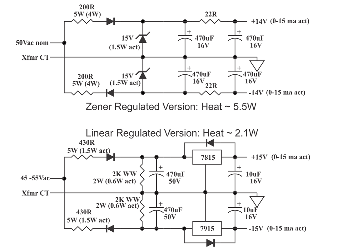
Thanks for the tip on the AC voltage. Here's an alternative linear regulated version that only wastes about half the power.
Edit: it struck me after I posted that a simple zener-MOSFET source follower might be almost as good. Mr. Simulator says it is, excepting for the small amount of ripple carried through. And it would make a really fine pre-regulator for a 7815/7915 pair, removing the voltage stress and cutting dissipation more, at the cost of ... well, more cost.
The issue that the amp designer was fighting was that he had too much voltage available (50Vac) and had to turn it into only +/- 14Vdc. 50Vac rectifies to about 71Vdc unless you play some tricks. The cheapest and most reliable way to get rid of all that voltage is to waste power in a resistor. But doing that leaves you with a big variation in the output voltage unless you regulate it somehow. I suspect he was told to use a zener instead of a linear regulator to save money.
The original circuit spends about 4W in heat. They used a 5W resistor to do this. A couple of 5W cement resistors I looked up showed that you could expect over 140C surface temp on a 5W resistor at that power - yep, blazing hot and instant skin burns. I suspect that the resistors don't have a long life at 80% of rated power either; nor does the PCB under them. It's a lowest-cost, shorter-life solution. I suspect that they thought that since this was just the power to opamps, it didn't have to be very clean or well regulated. In another bare-bones decision, they used 470uF 16V caps. I would not feel good using less than 25V caps for these.
The problem with linear regulators is that they can't withstand a huge amount of input voltage (with some exceptions - see below) so the obvious solution of a 7815 and 7915 positive and negative regulators can't be used. They have an absolute maximum input voltage rating of 35Vdc. So I used a resistor divider to cut the input DC voltage for the regs down to 35V by using a 430 ohm series and a 2k shunt resistor. This got the input voltage to the regs down to between 19vdc and 35vdc for loads of zero to 16ma. I found that the probable load on the 14V outputs is 16ma by simulating the stock circuit and loading it down until it produced 14V. I think this circuit could be hack-wired into the existing PCB holes, as it's pretty similar.
The gotchas on the linear reg version are:
- it will cost more, as you have to put in linear regulators, change to 470uF 50V caps, etc.
- If it fails, it will be the linear regs having too much input voltage. This could be protected against by putting 35V zeners across the 2K resistors. These would normally not conduct at all, but would save the regulators if the power transformer or AC power line goes mad.
In return, you save half the waste heat and the PCB will almost certainly not char. The opamps will be happier with their power supply, but then they weren't complaining (much...) as it was.
An alternate version could use a MOSFET or bipolar in front of the linear reg to drop some voltage. This would be the lowest-power version, as only the 16ma or so needed by the load would be conducted from the transformer tap. I can have a go at that if there's a lot of interest.
Re: Carvin X100 Schematic Verification and Ultra Hot Cement Power Resistors
Welcome.
Thank you for your interest in this amplifier and the info you have provided. This is first class stuff!
Greg
Re: Carvin X100 Schematic Verification and Ultra Hot Cement Power Resistors
Probably worth replacing the other electrolytics if you still have the amp. The low voltage types go bad too. Even if they are currently somewhat functional, it's worth it for the peace of mind. I bet it would cost you another $20. in parts, shipped, and take about an hour.
Re: Carvin X100 Schematic Verification and Ultra Hot Cement Power Resistors
Not in this power supply. This is half-wave with a 200R resistor in series with the diode. I would expect 16V to 17V at the first filter capacitor with a 50mA load and no zener diode. It doesn't take very much more current for the voltage to be under 15V at the first capacitor and the zener wouldn't make any difference.
Re: Carvin X100 Schematic Verification and Ultra Hot Cement Power Resistors
Hmmm. I thought I might have missed something, so I went back over my math and simulation.Ten Over wrote: ↑Wed Aug 30, 2023 2:51 amNot in this power supply. This is half-wave with a 200R resistor in series with the diode. I would expect 16V to 17V at the first filter capacitor with a 50mA load and no zener diode. It doesn't take very much more current for the voltage to be under 15V at the first capacitor and the zener wouldn't make any difference.
First, the sentence as I wrote it is correct. The peak value of a 50Vac sine wave is Vrms * 1.414. For 50Vac, the peak is 50 * 1.414 = 70.7V. A capacitor input power supply rectifies to the peak, minus any charging losses. The complete sentence is "50Vac rectifies to about 71Vdc unless you play some tricks." Mr. Simulator agrees.
But in this power supply, there are indeed tricks played. There is that 200 ohm resistor and a zener. The resistor does reduce the voltage available to the cap because of the voltage drop during the charging peak, and that depends on the loading. I tinkered the load up to 50ma with no zener diode, and it does drop. It's about 26.7Vdc. The cap charging current pulses hit 216ma in these conditions. That's with no zener and four times the expected load current. The peak of the charging current at 200ma wipes off 0.216A * 200R = 43.2V from the incoming 70V-ish peak.
With the zener in, the zener shaves off the incoming voltage at the zener conduction voltage and has a low zener resistance so when the incoming waveform hits the zener voltage, current shunts into the zener. Connecting the zener up changes things. The RMS current in the 200R goes to 135ma, the zener has 102ma RMS, and the DC voltage drops to about 14Vdc for the "15V" zener I have in the model. Output current is 28ma for the 500 ohm load I left in from the no-zener case. 135ma in a 2000 ohm resistor is 0.135 * 0.135 * 200 = 3.64W.
Changing back to a 1K load resistor gets 14.4V out and 14.4ma load current. The RMS current in the 200 ohm resistor stays at 134ma, and the zener current changes to 116ma. No surprise - in a zener regulator, the zener shunts any current the load doesn't need. All that happens in a lower load is that the zener current and dissipation goes up.
In this power supply, instead of a simple half wave rectifier putting out ~71V, the addition of the resistor lowers the output voltage to 26.7V with a 50ma load, and 53.4Vdc with a 14ma load. As expected, the DC on the output is highly, highly load dependent. Most opamps die with more than +/- 18V on their power supplies, so without the zener, the opamps are dead. Putting in the zener corrects the output voltage to roughly 15Vdc, and introduces high RMS currents in the 200 ohm resistor and zener, but saving the opamps that are the point of the power supply.
I can post screen shots of the simulator runs if you would like to see them.
Phew! I thought I'd missed something big.
Re: Carvin X100 Schematic Verification and Ultra Hot Cement Power Resistors
Did I say that your sentence was incorrect? No, I did not.
Now, I may well have implied that your sentence was irrelevant in the context of the power supply at hand. But worse than that, it could give some the impression that we will have to deal with beating 71Vdc down to 15Vdc, which we will not.
-
gui_tarzan

- Posts: 606
- Joined: Thu Jan 16, 2014 3:10 am
- Location: The 26th State
Re: Carvin X100 Schematic Verification and Ultra Hot Cement Power Resistors
That's one ugly solder job. I did better when I was ten. Is that black wire what's holding the can cap in place???

--Jim
"He's like a new set of strings, he just needs to be stretched a bit."
"He's like a new set of strings, he just needs to be stretched a bit."
Re: Carvin X100 Schematic Verification and Ultra Hot Cement Power Resistors
So I understand that to mean that you now agree that what I wrote was correct - right?
Yep, you for sure did that, at a minimum, while, as I understand now, not having any disagreement with the truth of the sentence. Is that correct?Now, I may well have implied that your sentence was irrelevant in the context of the power supply at hand.
And in doing so sidestepped away from what I was describing, which was a guess at what might have happened in the design shop to make them give us that circuit with the blazing hot resistors.
Actually, we're dealing with the reality - not impression - that we have to deal with beating 71V AC peaks down to 14Vdc, which the circuit surely does have to do.But worse than that, it could give some the impression that we will have to deal with beating 71Vdc down to 15Vdc, which we will not.
In the next sentence I started delving into what the circuit had done to avoid the unvarnished 71Vdc problem. I may have been too trusting, feeling like a reader having read one sentence would read the next one or two sentences, and not be confused by stopping reading too soon.
-
pompeiisneaks

- Site Admin
- Posts: 4222
- Joined: Sat Jan 14, 2017 4:36 pm
- Location: Washington State, USA
- Contact:
1 others liked this
Re: Carvin X100 Schematic Verification and Ultra Hot Cement Power Resistors
I hope this isn't getting as testy as it seems? be kind, rewind and all that.
~Phil
~Phil
tUber Nerd!
Re: Carvin X100 Schematic Verification and Ultra Hot Cement Power Resistors
Yup!gui_tarzan wrote: ↑Wed Aug 30, 2023 9:59 pm That's one ugly solder job. I did better when I was ten. Is that black wire what's holding the can cap in place???
Greg
Re: Carvin X100 Schematic Verification and Ultra Hot Cement Power Resistors
Thanks. If this was my amp, I would replace all of them too. I definitely will discuss this with the amp’s owner.maxkracht wrote: ↑Tue Aug 29, 2023 3:57 pm Probably worth replacing the other electrolytics if you still have the amp. The low voltage types go bad too. Even if they are currently somewhat functional, it's worth it for the peace of mind. I bet it would cost you another $20. in parts, shipped, and take about an hour.
Greg