
See scopeshots attached.
Left column: larger sine is post V2 signal, about 136v. Smaller wave is post PI. These are shown at the same scale. Post PI voltage is about 28. In second row, I have turned up the volume, driving the PI into clip. As I continue to open the volume pot, PI clip increases, and V2 amplitude drops, and wave becomes flattened.
Now, why does the volume control, which is AFTER V2, affect V2 when it's opened all the way? By changing the load on the plate? But there's a 0.047uF cap between the plate and the volume pot. Is the load changing on just some of the frequencies?
Right column: The tall sine is the same post-V2 signal. The other wave is the output of a power tube (OT primary, in other words). NOT at the same scale. The output trace is about 250v p-p.
Why all the jitter in this trace?
Monkeymatic Penta (Matchless Clubman inspired)
Moderators: pompeiisneaks, Colossal
Re: Clubman build
You do not have the required permissions to view the files attached to this post.
I build and repair tube amps. http://amps.monkeymatic.com
Re: Clubman build
Output question: Scope shows 17.5v p-p at 4ohm output. That's 6.2vrms. My DMM agrees, more or less, showing 7vac. This is with output waveform just before clipping. So that's only 12 watts. Shouldn't I be getting closer to 30 with two EL34s?
I build and repair tube amps. http://amps.monkeymatic.com
Re: Clubman build
If you're probe is on one of the PI plate resistors, I would expect a trace like this as you increase the volume (here's one I made earlierxtian wrote:Left column: .... As I continue to open the volume pot, PI clip increases, and V2 amplitude drops, and wave becomes flattened.
[IMG
 1000]http://i255.photobucket.com/albums/hh14 ... C_8954.jpg[/img]
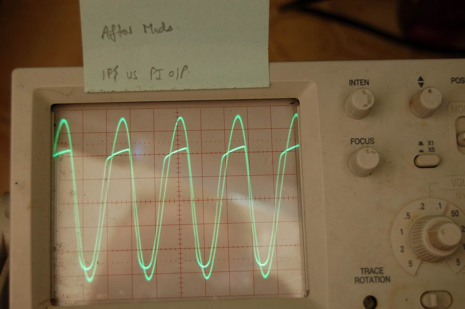
The sine wave is the input to the PI, and the clipped wave is the output at the anode/plate (the scales have been adjusted to overlay the traces).
What's happening here is that the positive part only of the PI output is being clipped because the voltage is greater than the bias voltage of the output stage - ie. the PI is trying to drive the grid of the power tube positive. There's a fairly abrupt transition from the sine wave to the (almost) flat top when this happens because current starts flowing into the grid and stops the voltage rising any further. (Actually, the coupling cap starts charging up, so the voltage at the PI does rise slowly).
The clipping I see in your traces looks symmetrical, so if these are from the PI plate, it looks to me like it is the PI clipping. Even in the first trace, you can see that the that the PI output is distorted from a true sine wave, which also leads me to believe that your PI is the limiting stage.
Pretty much - that cap is pretty much invisible to guitar signals.Now, why does the volume control, which is AFTER V2, affect V2 when it's opened all the way? By changing the load on the plate? But there's a 0.047uF cap between the plate and the volume pot. Is the load changing on just some of the frequencies?
Plug the capacitor value into a calculator ( like this ) and see what it's reactance[*] is at (say) 400Hz and compare this to the other resistances in that area. In this case, it's about 8K, and in series with the signal, so is insignificant compared to resistors measured in 100s of K. When you do this a few times, you start to get a feel for whether a cap is significant, or not in a particular situation.
[*] Think of it as an equivalent value resistor that looks the same to your chosen frequency of AC as the capacitor does.
With the volume down, the EF86 sees ~1M (ignore the little 150pF cap, because that will only be relevant for very high frequencies). With the volume up, the EF86 sees 1M in parallel with 220k in parallel with the 1M grid lead on the PI, or about 150K - that is a really heavy load for the EF86! It will drag the voltage right down (which might be where the MOJO comes from, so you don't necessarily need to 'fix' this).
Probably a ground loop - where have you connected the ground on the scope probe? You also sometimes get problems with ground loops through the AC mains ground. (An isolation transformer is the correct answer here - There is another one, but it's not recommended... yes, I know, I've done it tooRight column: ... Why all the jitter in this trace?
Just a heads-up - check the maximum voltage rating of your scope input and your probes if you're looking at the OT primary - there can be some very big voltages there (maybe 2x B+).
Your P-P to RMS conversion looks correct to me, and I also would have expected more than 12W from that circuit. Measuring into a dummy load is the way to do it.
There is *definitely* something cooky going on because of your lack of volts across the EF86 cathode resistor (there's ~~1.5mA going into the top of it, and nothing coming out the bottom...the electrons must be going somewhere ????). It is still giving plenty of signal to the PI, though, so not directly related to the low output.
It looks like your PI isn't giving enough output to drive the EL34s fully, but without knowing the scales of those traces, it's difficult to be certain. The EL34 datasheet will the drive reqirements for full output, so your PI will need to give at least that much output. (Actually, you say that the PI output is 28V P-P, so you're only seeing 14V peak to the EL34 grid, and you probably need about 35V - so 70V P-P)
Start by measuring your voltages everywhere around the PI (include the junction of the 4 resistors in the PI 'tail') and see if you can figure out what's going on. (You did correct the B+ dropper resistor for the PI at the same time as the preamp one, didn't you?)
HTH
Re: Clubman build
I just checked your photos, and it seems you did change the resistor, but I don't see the link from the +ve of the smoothing cap to the two 100K plate resistors on the PI - is it under the board?Tillydog wrote:You did correct the B+ dropper resistor for the PI at the same time as the preamp one, didn't you?
...or not...?
Re: Clubman build
Correct. And thanks for all your observations!! Too dang bad I have to work my day job. I'll chew on this soon.Tillydog wrote:is it under the board?
I build and repair tube amps. http://amps.monkeymatic.com
-
martin manning

- Posts: 13375
- Joined: Sun Jul 06, 2008 12:43 am
- Location: 39°06' N 84°30' W
Re: Clubman build
I'm gonna suggest that you get your DC issue sorted out before you spend too much time looking at AC signals... The horse goes before the cart, ya know? ;^)
Re: Clubman build
I hear you Martin!
I tried changing the screen grid (pin 1) resistor from 2M2 to 1M, thinking if I make this grid more positive, it will increase the current. It did increase the voltage on pin 1 from 36 to 51, but voltage at the plate (pin 6) dropped from 158 to 75! Still, no detectable DC at the cathode (pin .
.
I tried changing the screen grid (pin 1) resistor from 2M2 to 1M, thinking if I make this grid more positive, it will increase the current. It did increase the voltage on pin 1 from 36 to 51, but voltage at the plate (pin 6) dropped from 158 to 75! Still, no detectable DC at the cathode (pin
I build and repair tube amps. http://amps.monkeymatic.com
Re: Clubman build
I need to pause from building and check in here more often - I have one of these on tap too! Thanks for posting your build Xtian, I don't have anywhere near the chops of the folks on this board, but I have learned so much that I have an endless list of beers to buy for people. Mark and many others have been so generous and helpful.
I did my very sketchy preliminary layout for this quite some time ago with the intent of building it PTP. I've done a few PTP since then in an attempt to warm up, as I have a set of really nice transformers from Bob at TDS waiting patiently for this build. The lightning I did came out pretty good, but probably needs a bit of attention. I'll probably tweak that before I jump into this one. Anyway, thanks so much for documenting your work - I'll be sure to reference this and post anything I find that might be of use.
Great stuff!
-
JazzGuitarGimp

- Posts: 2355
- Joined: Mon Jul 23, 2012 4:54 pm
- Location: Northern CA
Re: Clubman build
I did a similar build a few years ago. The EF86 circuit was wired just like your schematic, and was borrowed from a /13 schematic that's floating around the 'net. I don't recall measuring the cathode voltage, but I did measure the gain of the stage and was surprised to see it was 250, which is the amplification factor as stated in the datasheet.
Lou Rossi Designs
Printed Circuit Design & Layout,
and Schematic Capture
Printed Circuit Design & Layout,
and Schematic Capture
-
martin manning
- Posts: 13375
- Joined: Sun Jul 06, 2008 12:43 am
- Location: 39°06' N 84°30' W
Re: Clubman build
If I take the EF86 Clubman schematic as posted, and the stated 418V supply, I get Va = 126, Vg2 = 96, Vk = 2.3. These are very close to the pin voltages listed in the table (131, 96, and 2.2). Cathode current is just over 1mA, and gain is 224/47dB.
-
martin manning
- Posts: 13375
- Joined: Sun Jul 06, 2008 12:43 am
- Location: 39°06' N 84°30' W
Re: Clubman build
A thought- do you have another EF86 to try in there?
Re: Clubman build
No. Certainly would have tried swapping early if I did. On one hand, I'd love to know what's going on with my EF86 voltages; OTOH, it's putting out such a lovely, toneful sound that I'm not motivated to change it.martin manning wrote:A thought- do you have another EF86 to try in there?
Then there's the PI, which is more important; distorts too early, and does not put out enough amplitude. If I wanted to emulate the PI values from a different schematic, what should I look at? 5f6a / 1987?
I build and repair tube amps. http://amps.monkeymatic.com
-
martin manning
- Posts: 13375
- Joined: Sun Jul 06, 2008 12:43 am
- Location: 39°06' N 84°30' W
Re: Clubman build
I don't understand why you would want to waste another minute tweaking a circuit that is not functioning correctly.
Re: Clubman build
Um, because it sounds good? But I guess you're suggesting there's a wiring fault (or defective tube) causing the issues, therefore, don't bother with tweaks until I solve this issue.martin manning wrote:I don't understand why you would want to waste another minute tweaking a circuit that is not functioning correctly.
I build and repair tube amps. http://amps.monkeymatic.com
Re: Clubman build
And wouldn't it be good to know what you've done to make it sound so good?xtian wrote:Um, because it sounds good? But I guess you're suggesting there's a wiring fault (or defective tube) causing the issues, therefore, don't bother with tweaks until I solve this issue.martin manning wrote:I don't understand why you would want to waste another minute tweaking a circuit that is not functioning correctly.
There's clearly current flowing from somewhere to produce that drop at the screen, but seemingly not coming from the cathode (at least not through Rk). Very odd.