
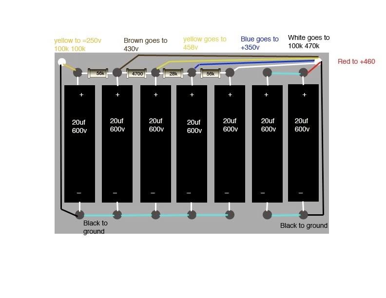
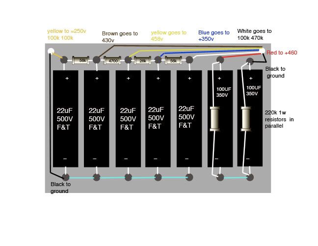
Need a set of experienced eyes on this please. The top diagram is the existing 6G4 filter cap setup. I am looking at going with the lower diagram. I t was suggested that I try 100uf/350v for the first two caps in series with a 220k 1 w resistor in parallel on each cap.
The original schemo calls for 56K where that 28k resistor is now. Thats what I found in the amp. Leave that 28k on the yellow wire?
white dots are the pass through to the inside of the chassis.
[IMG:792:612]http://i260.photobucket.com/albums/ii9/ ... layout.jpg[/img]
[IMG:648:501]http://i260.photobucket.com/albums/ii9/ ... -recap.jpg[/img]
Recap check - old fender
Moderators: pompeiisneaks, Colossal

Re: Recap check - old fender
The capacitor on the far right should have the polarity reversed. Otherwise it looks ok.
I Think I Think Too Much !

Re: Recap check - old fender
The 220K resistors are bleed resistors. They are there as a safety measure. After you turn off the amp, these will bleed the caps. It takes a few minutes for them to work. Otherwise, they don't affect anything.
A pair of 100uf caps in series is 50uf. The limit for a GZ34 is 60uf, so that should be fine. The schematic shows a pair of 20uf in parallel, wich is 40uF. I'm not sure you'd notice much difference. It's more likely you'll notice the difference because the caps have been renewed. Remember to use caps of adequate voltage rating.
A pair of 100uf caps in series is 50uf. The limit for a GZ34 is 60uf, so that should be fine. The schematic shows a pair of 20uf in parallel, wich is 40uF. I'm not sure you'd notice much difference. It's more likely you'll notice the difference because the caps have been renewed. Remember to use caps of adequate voltage rating.
corrected -
I missed that polarity, thanks. Phil, so those bleeders are done correctly? In the Dlite they bridge the eyelets. Could it be done that way as well? The 100uf are 350v but they feed a 458v node. I understand that the voltage is
summed when they are in series.
[IMG:648:501]http://i260.photobucket.com/albums/ii9/ ... ecap-1.jpg[/img]
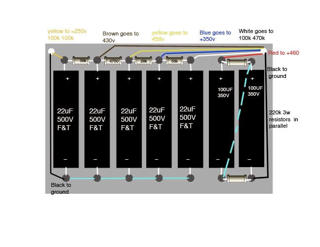
or this Alternate method like the Dlite
Ok thanks Martin.
[IMG:648:501]http://i260.photobucket.com/albums/ii9/ ... ecap-4.jpg[/img]
summed when they are in series.
[IMG:648:501]http://i260.photobucket.com/albums/ii9/ ... ecap-1.jpg[/img]
or this Alternate method like the Dlite
Ok thanks Martin.
[IMG:648:501]http://i260.photobucket.com/albums/ii9/ ... ecap-4.jpg[/img]
Last edited by angelodp on Fri Jan 29, 2010 11:59 pm, edited 1 time in total.
-
martin manning

- Posts: 13250
- Joined: Sun Jul 06, 2008 12:43 am
- Location: 39°06' N 84°30' W
Re: corrected
Yes, put the cap on the far right back the way you had it (positive end up), move the resistors so they bridge the eyelets top and bottom, and then move the blue jumper so that it goes from lower left to upper right. The ground wire now goes back where it was in the original layout, extreme lower right.angelodp wrote:In the Dlite they bridge the eyelets. Could it be done that way as well?
MPM
(edited for grammar)
Last edited by martin manning on Sat Jan 30, 2010 1:20 pm, edited 1 time in total.

Re: Recap check - old fender
Not only: they balance the two caps by giving a current path, thus mitigating leakage resistance. As a rule of thumb those R's should pass 1 mA or so for most MI amps, roughly x10 max cap current leakage.The 220K resistors are bleed resistors.
Re-corrected
Thanks guys.. Looks like I am there.
Re: Recap check - old fender
Yes but the schematic has two 20uF 600v caps in parallel for the first filter.
I would agree it may be a better filter having the two caps in series but to be original they are in parallel with no resistors.
I would agree it may be a better filter having the two caps in series but to be original they are in parallel with no resistors.
You do not have the required permissions to view the files attached to this post.
Tom
Don't let that smoke out!
Don't let that smoke out!
-
martin manning
- Posts: 13250
- Joined: Sun Jul 06, 2008 12:43 am
- Location: 39°06' N 84°30' W
Re: Recap check - old fender
This didn't get addressed... You should keep the resistors as they are.angelodp wrote:The original schemo calls for 56K where that 28k resistor is now. Thats what I found in the amp. Leave that 28k on the yellow wire?
MPM
-
RightLurker
- Posts: 91
- Joined: Sat Dec 19, 2009 3:00 pm
Re: Recap check - old fender
For those who may be interested, Weber VST stocks 20uf 600 volt electrolytic caps, that seem to work fine in my Bassman.
great info
RightLurker, great info and they are quite reasonably priced at $2.00 each
WOW!! and you say they work fine in your rig. Thats hard to beat. One wonders why these caps range so much in price $12.00 for the Sprague Atom!
WOW!! and you say they work fine in your rig. Thats hard to beat. One wonders why these caps range so much in price $12.00 for the Sprague Atom!
Re: Recap check - old fender
Pre-CBS Fenders do not always match their respective schematics. Leo was always tweaking... I've seen some unusual stuff from time to time, like a blonde Showman with a plate load resistor on V1 consisting of a 220k and 100k in parallel, the eyelet boards was even modified for this tweak, it was stock, but not on the schematic...
If you find your old Fender with different value components as built from the factory why not leave them as is, you've got a bit of Fender amp history there!
TT
If you find your old Fender with different value components as built from the factory why not leave them as is, you've got a bit of Fender amp history there!
TT
Re: Recap check - old fender
Yeah, I have read that if Fender was out of a certain part, instead of waiting for the part to arrive they would simply substitute another value if it wasn't critical to the amps operation.
Using up old tube charts before making new ones is another classic Leo move.
A very frugal man.
Using up old tube charts before making new ones is another classic Leo move.
A very frugal man.
Tom
Don't let that smoke out!
Don't let that smoke out!
original
Tictac, yes indeed I am trying to stay with the all of the original stuff if I can. I was advised to change out the filter caps as they are 50+ years old. The small cap on the intensity knob seemed to be leaking so I pulled it. I also have an output tranny that is wrecked looking but runs fine. It has been epoxied and gooped. Is there a good reason to replace it. It sounds fine.
[IMG 1080]http://i260.photobucket.com/albums/ii9/ ... uperOT.jpg[/img]
[IMG
 1080]http://i260.photobucket.com/albums/ii9/ ... uperOT.jpg[/img]
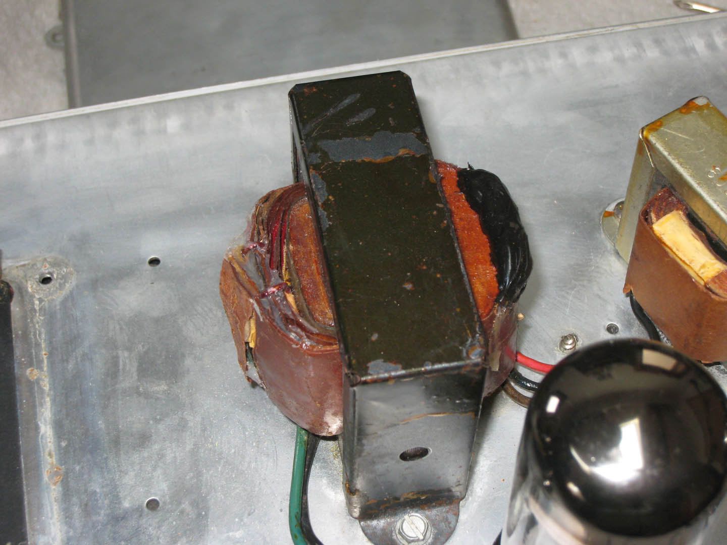
Re: original
Don't fix it until it's broken. Leave it alone.angelodp wrote: I also have an output tranny that is wrecked looking but runs fine. It has been epoxied and gooped. Is there a good reason to replace it. It sounds fine.