Effect Pedal building

General discussion area for tube amps.

Moderators: pompeiisneaks, Colossal

Post Reply
User avatar
Structo
Posts: 15446
Joined: Wed Oct 17, 2007 1:01 am
Location: Oregon

Re: Effect Pedal building

Post by Structo »

Thanks Tele.

I learned my lesson building PNP effects.

Inevatibly, I or someone plugs a negative center adapter into it either frying the pedal or the power supply. :oops:
So I try to go NPN if I can.

That being said there seems to be a worldwide shortage of decent NPN Germaniums.
Tom

Don't let that smoke out!
tele caster
Posts: 189
Joined: Sat May 24, 2008 5:17 pm

Re: Effect Pedal building

Post by tele caster »

I thought your layout was positive ground. I don't see it anymore.
User avatar
Structo
Posts: 15446
Joined: Wed Oct 17, 2007 1:01 am
Location: Oregon

Re: Effect Pedal building

Post by Structo »

I think it may be copyrighted, it was X'd out.

They have PNP, NPN layouts and schematics.

You have to join to use the forum but it's free and painless.

www.guitarpcb.com

http://www.guitarpcb.com/apps/forums/

http://www.guitarpcb.com/apps/forums/to ... buzzaround
Tom

Don't let that smoke out!
tele caster
Posts: 189
Joined: Sat May 24, 2008 5:17 pm

Re: Effect Pedal building

Post by tele caster »

I'm not surprised it was x'd. I don't recommend joining that site unless you like getting spammed. :roll:
User avatar
dorrisant
Posts: 2628
Joined: Tue Sep 21, 2010 1:27 pm
Location: Somewhere between a river and a cornfield
Contact:

Re: Effect Pedal building

Post by dorrisant »

Check this out... Ross type compression pedal with Hammer mod and a few other tweaks.

[IMG:432:766]http://i946.photobucket.com/albums/ad30 ... 044554.jpg[/img]

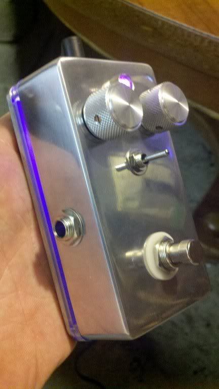
I need to brighten up the LED for the acrylic plate and do some acid etched graphics. Still waiting for a couple parts but it looks pretty good so far.
"Education is what you're left with after you have forgotten what you have learned" - Enzo
User avatar
Structo
Posts: 15446
Joined: Wed Oct 17, 2007 1:01 am
Location: Oregon

Re: Effect Pedal building

Post by Structo »

Looks great1

I've been wanting to pimp out a pedal with that glowing base for a while.

What did you use for the spacer?

I built a combo Dyna-Ross Compressor a while back.

It's really only a few different values and caps that make the Ross different.

I've been diggin' the 5 Knob Comp from BYOC lately.

Here's the one I did.

It has three way Attack switch and the Dyna/ Ross selector switch.

[img:640:512]https://lh6.googleusercontent.com/-O3vA ... nished.jpg[/img]
Tom

Don't let that smoke out!
User avatar
dorrisant
Posts: 2628
Joined: Tue Sep 21, 2010 1:27 pm
Location: Somewhere between a river and a cornfield
Contact:

Re: Effect Pedal building

Post by dorrisant »

I got the acrylic here...

http://www.smallbearelec.com/servlet/Detail?no=1168

It is from thetonegod.com... I'm looking at how to make these in-house though. A bit sloppy on the fit but overall really nice. They also have them for 1590BB too.

How many poles on that Dyna/Ross switch?

Tony
"Education is what you're left with after you have forgotten what you have learned" - Enzo
User avatar
David Root
Posts: 3540
Joined: Fri Aug 04, 2006 3:00 pm
Location: Chilliwack BC

Transistor Color band codes

Post by David Root »

Tom, that looks really good!!

Just received my start up shipment from Small Bear Electronics. The 2N5088s have three color bands on the round side. A purple band on all of them, some have green as well, some other colors.

What is the significance of these color bands? Is it another way of indicating the gain of the particular part? I also got some 2SC1949s and their flat side is marked R which I know is a gain notation.

Maybe the color bands are a duplication for folks with poor eyesight if the letter notation is hard to read?

Couldn't find anything on the web about this. I attached a pic of a '75 Dynacomp board that shows these color bars.
You do not have the required permissions to view the files attached to this post.
Last edited by David Root on Wed May 16, 2012 11:16 pm, edited 1 time in total.
User avatar
Colossal
Posts: 5048
Joined: Sat Oct 20, 2007 9:04 pm
Location: Moving through Kashmir

Re: Effect Pedal building

Post by Colossal »

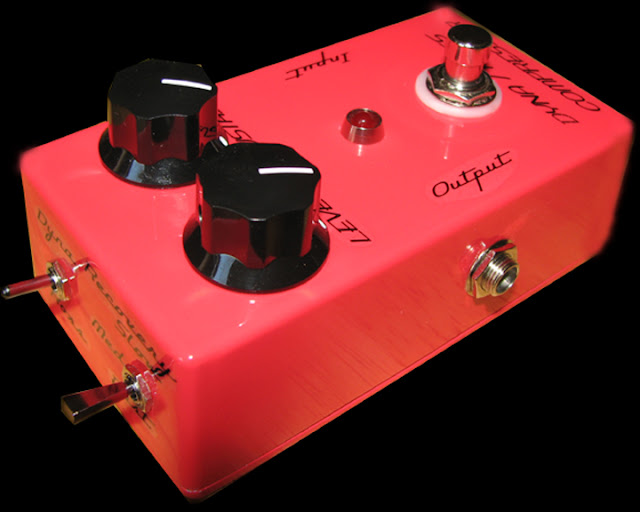
Holy sh!t Tom, that Dynacomp is killer! Really nice work on that. Did you use one of Mammoth's powder coated boxes? I've been eyeballing that site since you posted the link to their site. It's a little hard to tell from the photo, but is that red close to the original script Dynacomps or is it more watermelon colored? Did you use water slide decals and shoot a clear coat over that? I am getting parts for a Dynacomp clone!

Great job!!
User avatar
ampmike
Posts: 1547
Joined: Tue May 05, 2009 3:18 pm
Location: Bangor Pa
Contact:

pedals

Post by ampmike »

Well I just started reading through this thread this morning.Oh my Gosh!!
This could be my next adiction Thanks Guys :D
User avatar
Structo
Posts: 15446
Joined: Wed Oct 17, 2007 1:01 am
Location: Oregon

Re: Effect Pedal building

Post by Structo »

Dorrisant,
Do you have to use separate LED's to light the plate?

The Dyna/ Ross switch is two position, either or.

I think this is where I got my red box.

http://www.smallbearelec.com/servlet/Detail?no=706

Yes waterslide decals and clear coat.
The decals weren't that great as they didn't lay down real well.

I actually prefer my BYOC 5 Knob Compressor over this one.

David,
That is the first time I have seen color codes on transistors.

Not sure how the code works but it is mentioned here.
http://transistorhistory.50webs.com/xstr.html

[img:266:323]http://www.semiconductormuseum.com/Phot ... age002.gif[/img][img:300:299]http://transistorhistory.50webs.com/1740c.jpg[/img]

On the right is a closer look at the business end of the WECO 1740 photocell. Bevitt indicates that the tiny package is made of clear plastic with all faces but one painted black, leaving a transparent window on top revealing the single-crystal bar of germanium. The PN junction is in the middle and forms the photoelectric element. One side also has a swatch of white to make the identification paint dots more easily readable. The yellow dot on the end signifies the positive lead for the biasing circuit. The purple-yellow-black dots on the side use the same color code as resistors which translates to 7-4-0, with the leading "1" being implied
Tom

Don't let that smoke out!
User avatar
dorrisant
Posts: 2628
Joined: Tue Sep 21, 2010 1:27 pm
Location: Somewhere between a river and a cornfield
Contact:

Re: Effect Pedal building

Post by dorrisant »

Tom, two separate leds. The one for the acrylic plate stays on to indicate power is on and is fed through a 330 ohm resistor. The indicator led on the top is switched and fed via 2k2 so as to not cause blindness... both pink (?) leds from Radio Shock. I say pink (?) because it looks purple to everyone.

The two switches on the front end of your comp pedal remind me of a dual exhaust on a VW bug... very cool!

Built a BuzzAround alike... NPN silicone/germanium hybrid Buzzaround. I can't believe how nice it sounds! Highly recommended.

Next up... Tremulus Lune. After that, a Tycobrahe Octave Fuzz.

All wonderful additions to the front end of a Rockster.

Tony
"Education is what you're left with after you have forgotten what you have learned" - Enzo
User avatar
Structo
Posts: 15446
Joined: Wed Oct 17, 2007 1:01 am
Location: Oregon

Re: Effect Pedal building

Post by Structo »

Hey, since you built a buzzaround.

Is yours the Opamp one?

Did you add the master volume mod?

I had a hell of a time finding the right combination of transistors that would work.

I have two old top hat 2N1086 for Q1 and Q2 and a AC176 for Q3.

I get decent fuzz but not much louder than the bypass.

I used the pcb from guitarpcb.com so not real sure if it is correct.

The Timbre, Balance doesn't do much at all and the Sustain seems to be a bias of sorts. The volume works.

So for it to sound good I have to have all the pots dimed.

Weird.
Tom

Don't let that smoke out!
User avatar
dorrisant
Posts: 2628
Joined: Tue Sep 21, 2010 1:27 pm
Location: Somewhere between a river and a cornfield
Contact:

Re: Effect Pedal building

Post by dorrisant »

Tom,
Yes I did use the circuit with a TL072 op amp... without the additional volume control. The second half of the op amp is an output buffer that helps to not kill the output signal. I made my own pcb for it. I have a couple of tweaks to add to the layout for the next board, but I will post it here if you would like to use it. It sounds great! Everyone that has played through it is really digging it.

http://freestompboxes.org/viewtopic.php?f=13&t=9401


Tony
"Education is what you're left with after you have forgotten what you have learned" - Enzo
User avatar
cbass
Posts: 4356
Joined: Sat Jul 23, 2011 6:17 pm
Location: Between Pomona & Bakersfield

Re: Effect Pedal building

Post by cbass »

My friend is making up some boards for me.For the Ross phaser project at Tonepad.

I'm gonna build one with the extra stages and one with the Univibe mods.

I've got an origional one that I tried the auto wah mod that sounded pretty cool.

I've also built a few other effects Fuzzface,EA tremolo,Couple of Rangemasters,Orange squeezer.All on pad-per hole board and mounted in an electrical box enclosure.I don't use them that often though.
Post Reply