Hey Guys,
I have an early model V4. Recently in the middle of practice the amp experienced loss of output. I removed the chassis from the cabinet, took a look at the main board, and saw that R52 & R53 appeared burnt. I replaced both of these resistors (correct value & wattage), but this still didn't fix the issue. Checked the plate & screen voltages (535VDC & 530VDC) which seemed normal. Tried to get a voltage reading on the pads/eyelets where these resistors are soldered and noticed that these resistors are getting so hot that they are literally melting the solder....
I'm guessing that something is causing excessive current draw? Any ideas?
I've built a few amps in my time, so I know the correct safety precautions when working on a tube amp, but my repair experience is less than experienced.
Thanks!!!!
Ampeg V4 Burnt Resistors
Moderators: pompeiisneaks, Colossal
Re: Ampeg V4 Burnt Resistors
Since R52 and R53 are dropping resistors in the B+ rail, my first suspicion would be that one or more sections of the C17 filter cap are beginning to short. That would account for high current draw. But what is happening the R51? If that resistor is also heating up, the problem might be a short downstream of the caps; possibly a bad tube in V3, V201 or V1, or an actual wiring short in that section of the amp.

Re: Ampeg V4 Burnt Resistors
if the amp still has the factory caps it's time to do a cap job. The bias section on these amps is very fragile. the PCB traces also lift off the board with heat since the tubes are inverted the heat builds up and the amps fail quicker then others. not to mention the high voltages used. Test the tubes. test continuity for shorting components due to the PCB. if you live in a moist climate they can also absorb water and be slightly conductive. as suggested test the Tubes and replace the caps, if new caps, test for leakage. the values used in the amps are solid when the amp is operational it's a very solid design just shitty material. If you need a replacement 6K11 tube or yours tested PM me.
My Daughter Build Stone Henge
Re: Ampeg V4 Burnt Resistors
Thanks for the advice guys.
C17 has been replaced by a previous tech. The other PS stages are original though, and should probably be replaced as well. R51 is not heating up like R52 & R53.
This amp was definitely worked on previously, and I must admit that it's a bit of a rats nest. Not to mention the cruddy early generation PCB's.
The 6550's currently in the amp are a VERY old quad of GE's (yes the screen resistor values have been changed), so I'm probably going to check out the bias supply, and then install a newer quad of 6550's that I have laying around. Though I'm not sure if this would explain the loss of output.....
Re: Ampeg V4 Burnt Resistors
Something interesting that I just noticed.
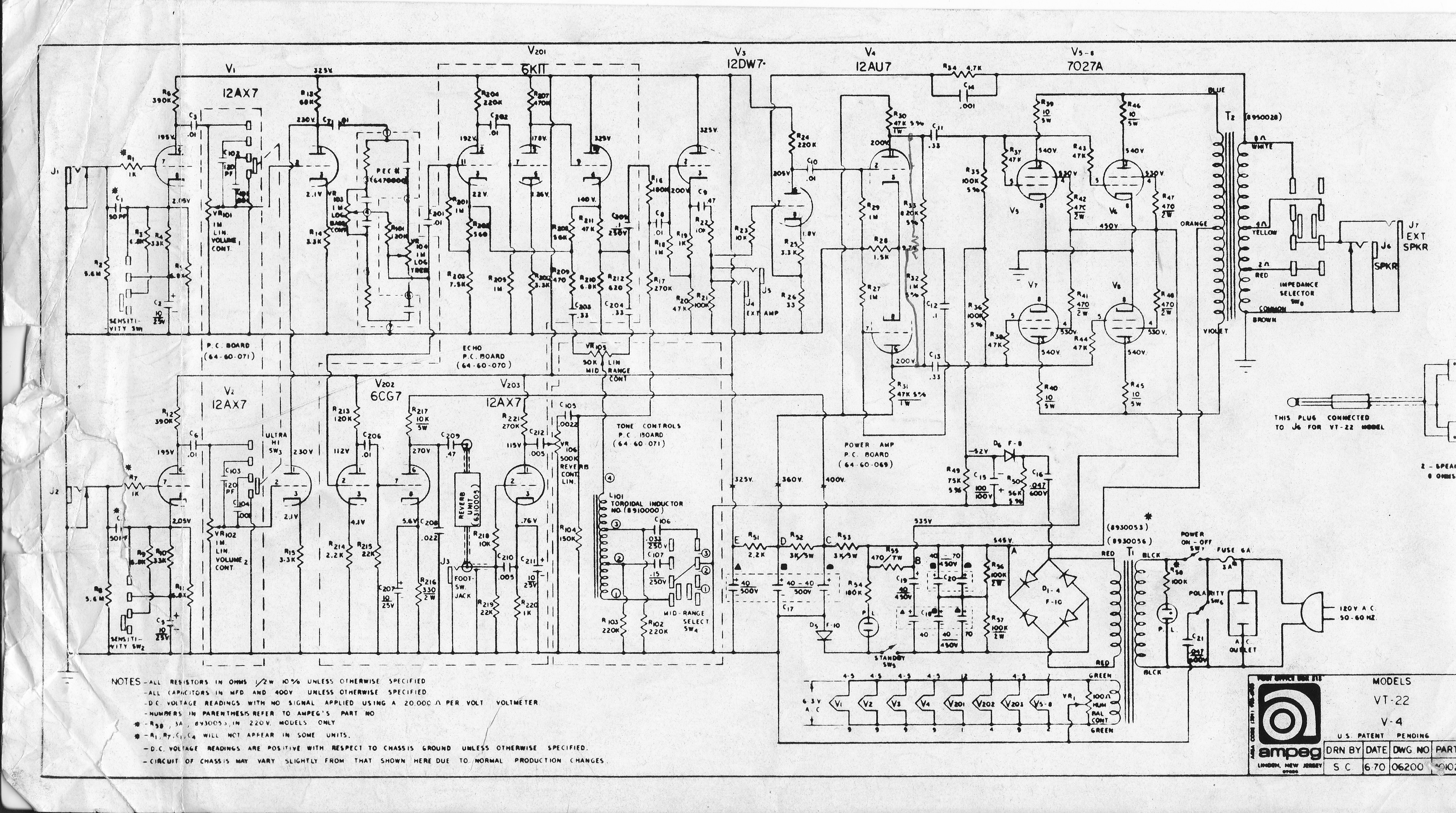
The V4 I'm working on is an earlier model that follows this schematic:
http://www.ampegv4.com/images/schematics/V4.jpg
This model does not have the series diodes coming off the OT plate windings like the later version:
http://www.freeinfosociety.com/electron ... mpegv4.gif
Apparently the person who previously worked on this amp installed these diodes, but only connected them to the (-) output of the bridge rectifier, and didn't also connect them to the (+) output of the rectifier. If I'm reading the second schematic correctly, they connect to (A), which is both the positive and negative outputs.
Any thoughts?
Re: Ampeg V4 Burnt Resistors
FIXED!!! Thanks Firestorm & selloutrr, you were right. Since that cap had been replaced, I just assumed that they were not the issue. The PS cap on stage D had shorted, thus the PI was not getting any voltage. Changed out that cap, and my amp is alive again!!! Thanks!
Re: Ampeg V4 Burnt Resistors
Glad to hear you got it working. As to the diodes, be careful, the schematic is terrible in that regard; there are two "A"s, they are NOT the same. The diodes go from the ends of the OT windings to the rectifier's minus output (which is also at ground). They do not also go to the plus output (you would be shorting the rectifier if you did that). Don't be so sure your diodes were added by a tech. They seem to have been an Ampeg afterthought and the factory installed ones look like they were added in someone's garage.chuckrock wrote:Apparently the person who previously worked on this amp installed these diodes, but only connected them to the (-) output of the bridge rectifier, and didn't also connect them to the (+) output of the rectifier. If I'm reading the second schematic correctly, they connect to (A), which is both the positive and negative outputs.
Any thoughts?
Re: Ampeg V4 Burnt Resistors
Thanks for the advice firestorm. I'll leave the diodes hooked up as they are. The amp sounds great now!!