Im hoping someone can clear the air for me concerning placing a cap and a resistor between OT primaries, and the accompanying switch. I'm just now digging into the concept as a 47n 630V film and 5.6K 1W has totally smoothed out the overdrive in a SE 6V6 build. 350V plates.
R/C : how does one determine the resistor wattage here? What is the formula to determine the cutoff frequency? Same as any other low-pass?
I believe for the cap, voltage should be 2x plates, to account for peaks?
Switch: this just seems dangerous to me, for no good reason , as every power switch on every amp has the same HT sitting on it, right?
How do I select a switch with the proper power and voltage rating? Does a good ol Carling 3A 125VAC/250VDC work here? My mini toggles are 6A at 125VAC, but no DC rating. Do I dare use one of those?
What's the best orientation for this network? I'm thinking plate>cap>resistor>switch>B+1 . Or switch between cap and resistor?
Thanks,
Jeremy
Conjunctive filter
Moderators: pompeiisneaks, Colossal
Re: Conjunctive filter
Here is a link to a discussion here from 2007
http://ampgarage.com/forum/viewtopic.ph ... 160f35835c
http://ampgarage.com/forum/viewtopic.ph ... 160f35835c
-
Smokebreak
- Posts: 1391
- Joined: Tue Dec 18, 2012 5:53 pm
- Location: Texas
Re: Conjunctive filter
Thanks Andy. I read that thread along with a bunch of others, as well as Steve Aloha's report :http://www.blueguitar.org/new/articles/ ... uesxpl.pdf
My questions are more pointed to how one would arrive at switch ratings and resistor ratings for the filter, as it seems folks just "shoot high" but I can't really find an explanation. I could throw a 10W resistor in there with a 10A switch, but space is at a premium here.
My questions are more pointed to how one would arrive at switch ratings and resistor ratings for the filter, as it seems folks just "shoot high" but I can't really find an explanation. I could throw a 10W resistor in there with a 10A switch, but space is at a premium here.
-
iknowjohnny
- Posts: 1070
- Joined: Thu Apr 24, 2008 2:10 am
- Location: los angeles
Re: Conjunctive filter
I'm glad this thread appeared, as it's been a long time since i tried this. I recall feeling it was like a blanket over the speaker effect as many others describe it. But it just hit me i never tried it with a small cap like in the pf range and I was thinking this could be worth a try. I like what bright gain stages do for the tone, but when it gets to the power section it's then pretty bright/harsh as you turn it up. There are cut controls and nfb, but they all work differently and i think there may be an advantage to the conjunctive filter because it's closer to the end of the chain. I find with nfb or cut controls, as i turn them to remove excessive/harsh highs, they take the volume down quite a bit. Then when i turn the master up to get the volume back to where it was before i cut, the brightness and/or harshness i removed now comes back along with the volume ! So in the end it seems like cut controls and nfb don't really work. A CF is what it is at any volume. so theres no such affect.
thanks for posting this, i'm going to try it with small caps starting with about 2200pf on down to 500 and see if it will smooth out the high end just enough without doing the blanket over the speaker thing.
thanks for posting this, i'm going to try it with small caps starting with about 2200pf on down to 500 and see if it will smooth out the high end just enough without doing the blanket over the speaker thing.
Re: Conjunctive filter
You forget the primary is an inductive load. When the power amp is overdriven the voltage can easily peak up waaaayyy past 2xB+. In fact, it can peak up to amplitudes that punch through tube sockets or even isolations of the OT windings. In other words, the voltage rating must be very, very high unless you want the capacitor to fail periodically. Probably needs to be either X or Y type and most definitely needs to be suited for AC applications.I believe for the cap, voltage should be 2x plates, to account for peaks?
You can use the same principle for the switch: HIGH voltage rating is mandatory.
I'd toss a waterbird with one. Those aren't good (read: safe) even for switching mains voltage. Those type of switches are generally used in 9V stompboxes.Does a good ol Carling 3A 125VAC/250VDC work here?
Re: Conjunctive filter
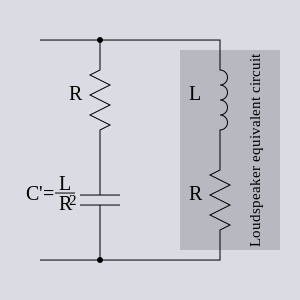
You have to ask yourself whether you are designing a tone control or a conjunctive filter. A conjunctive filter compensates the rising impedance of the speaker load (inductive reactance increases towards high frequencies). Thus a properly designed conjunctive filter is matched to the speaker load so that the outcome is flat-ish impedance at higher frequencies.What is the formula to determine the cutoff frequency?
The purpose is the same as for a Zobel network and I think all you need to do is to scale the values so that the circuit matches the higher impedance of the primary. The ordinary zobel (parallel to speaker load and specifically one that works effectively correcting a lot of the inductive characteristics) is calculated as follows: Series resistance is chosen to be close to nominal impedance of the speaker (e.g. 8 ohms for 8-ohm speaker). Capacitance is then calculated from:
C=Le/R^2
Where Le is inducatance of speaker's voice coil. (Consult speaker's datasheet if you don't know it).
[img:300:300]http://upload.wikimedia.org/wikipedia/c ... on.svg.png[/img]
Naturally, if you move such circuit from secondary side to primary side you need to scale impedance accordingly.
Alternatively, in push-pull amps one can split the filter across each primary side. Both naturally need to be scaled accordingly. This will halve the voltage across the filter as well as the losses.
Usually you see more generic Zobel values like 100nF + 10R (on secondary side), which are not as effective in compensating the whole inductive characteristic but work way above audio range. It's amatter of choice which design route you choose to take. Total compensation works better for crossover systems and alike while the "allaround" values are usually sufficient enough for generic applications. The response of both is naturally way different. Quite possibly the "generic" Zobel is designed such that you won't hear any of its effects, while the effects of the "flat" Zobel tend to be easily audible (at least when the power stage gets overdriven).
Note that the more effective zobel needs to shunt more higher frequencies so it will have much more losses across it. The generic Zobel is usually stressed only when the amplifier either oscillates or creates transients, like when the amplifier clips and/or has crossover distortion.
Why I refer to this? It's probably best explained by this:
http://www.earlytelevision.org/damper.html
Look at figure #3. Does it look familiar? When power tube goes into cutoff the magnetic field in output transformer (and any inductive component within the load) collapses and causes flyback transient or oscillatory ringing. The phenomenon is very much dependent on inductive properties of both load and transformer. Think about overdriving the amp to point where bias drifts to sustained grid conduction and crossover distortion: the field collapses always in the crossover region portraying the aforementioned symptoms. Since they are dependent on OT specs same OTs do not "buzz" as much as others. Since the phenomenon is also dependent on inductive properties of the load compensating them with the Zobel/Conjuctive filter can greatly decrease "buzzing". This is the main effect I have observed in amps like Carmen Ghia: The conjuctive filter has greatest effects in taming down ringing on amplifier's crossover regions when the amp is overdriven tremendously. (And CG and its origin, the Hammond circuit, are horrible permormers in regard of behaviour at crossover regions. Much more so than, say, generic Fender or Marshall-ish circuits). Now did someone wonder about why the "Paul Ruby Zener Mod" worked well in some amps and not so well in others and how that was related to OT. Think no more. You had the answer right there.
http://www.paulamps.com/18watterbuzz.html
Since the task of Zobel/Conjuctive filter is easily demanding in worst scenarios the resistor should be flame-proof type and the capacitor self-healing. (In worst case scenarios the filter needs to dissipate the entire power the amp is capable of outputting). Putting the circuit to primary side introduces its own demands because the voltage levels are highly increased and because many tube amplifiers with poor damping tend to have high transients in the primary side of the OT when overdriven. Not as bad as without load but effectively very close to that. Amps without "catch diodes" on output tube plates will naturally perform far worse in this regard and the filter needs to be extra tough in that case.
Personally I don't understand why not just solder a cap and a resistor across the speaker terminals (or fit it to secondary side in general). It's effectively the same circuit BUT without the ludicrous requirements putting it to primary side introduces. We don't live in 1933 anymore (when the conjuctive filter was first published in RCA manual and henceforth copied mostly by folks who didn't even understand what it was and how it worked) and we don't have to use designs introduced in 1933.
Oh, the Zobel or Conjuctive Filter will only compensate for the rising inductance. It will not compensate for rising impedance at resonant frequency of the speaker. That one would need another type of circuit.
Last edited by teemuk on Fri Dec 06, 2013 4:58 pm, edited 5 times in total.
-
iknowjohnny
- Posts: 1070
- Joined: Thu Apr 24, 2008 2:10 am
- Location: los angeles
Re: Conjunctive filter
I know some might roll thier eyes when i ask this after all the highly technical talk, but it's mostly over my head so please don't kill me. If as teemuk says a filter on the secondary side will do the same thing but require different values, can anyone suggest a good R/C starting point for a 50w EL34 JCM800 style amp? Thanks.
Re: Conjunctive filter
Did you really read my post? I think it clearly has all the math and information concerning the "starting point". It's pretty tough to express it any clearer than that.can anyone suggest a good R/C starting point for a 50w EL34 JCM800 style amp?
I'm out, thank you.
-
iknowjohnny
- Posts: 1070
- Joined: Thu Apr 24, 2008 2:10 am
- Location: los angeles
Re: Conjunctive filter
Sorry, i just have zero math skills and little elec theory.
Re: Conjunctive filter
Math in that is stupid simple, really.
This site has nice illustrations about the theory behind:
http://www.trueaudio.com/st_zobel.htm
This site has nice illustrations about the theory behind:
http://www.trueaudio.com/st_zobel.htm
Re: Conjunctive filter
Jeez, could you be a little more rude please.teemuk wrote:Math in that is stupid simple, really.
-
martin manning

- Posts: 13210
- Joined: Sun Jul 06, 2008 12:43 am
- Location: 39°06' N 84°30' W
1 others liked this
Re: Conjunctive filter
Teemuk, thanks for the in-depth post, and the link to more on the subject on RTA 's site (which in turn leads to more tech info). It's not at all unusual for a "simple" question to open a more in-depth discussion, which has benefits for other readers at all levels.
-
Smokebreak
- Posts: 1391
- Joined: Tue Dec 18, 2012 5:53 pm
- Location: Texas
Re: Conjunctive filter
Thank you for the detailed responses.
Personally, I'm ditching this for now and gonna look at my preamp to help with the bit of fizz I'm hearing. Mine is high mids, though.
I have always wondered about these, as aren't they the ones Fender used for mains AND standby, and that every DIY house sells as "power switches?teemuk wrote:I'd toss a waterbird with one. Those aren't good (read: safe) even for switching mains voltage. Those type of switches are generally used in 9V stompboxes.Does a good ol Carling 3A 125VAC/250VDC work here?
I tried a lot of values yesterday, and on a SE 6V6, found that 3300p and 10K on primary was a good compromise, but that any values that did tame the treble(even the slightest bit), brought the blanket with it. Anything was just too much for clean sounds, but I will say that at really high gain settings, it produced a very smooth, singing lead tone.iknowjohnny wrote: thanks for posting this, i'm going to try it with small caps starting with about 2200pf on down to 500 and see if it will smooth out the high end just enough without doing the blanket over the speaker thing.
Personally, I'm ditching this for now and gonna look at my preamp to help with the bit of fizz I'm hearing. Mine is high mids, though.
Re: Conjunctive filter
I don't care about that. The voltage and current ratings are way too low for those tasks. In addition, such application should NEVER use switches with metal body.I have always wondered about these, as aren't they the ones Fender used for mains AND standby, and that every DIY house sells as "power switches?
What Fender might have used back in the days might have complied with safety standards of those days. Those safety standards were, for example, ok with equipment that had no isolation transformers at all. Today most of those old-fashioned standards are a strict no no.
As said, I use these types of switches in 9V stompboxes and other low voltage circuits. I would never fit them to mains or other high voltage circuits and the 3A current rating is way too low for the surge currents switches in such applications will be exposed to.
Re: Conjunctive filter
Could we have an example here please?teemuk wrote: ↑Fri Dec 06, 2013 9:54 amYou have to ask yourself whether you are designing a tone control or a conjunctive filter. A conjunctive filter compensates the rising impedance of the speaker load (inductive reactance increases towards high frequencies). Thus a properly designed conjunctive filter is matched to the speaker load so that the outcome is flat-ish impedance at higher frequencies.What is the formula to determine the cutoff frequency?
The purpose is the same as for a Zobel network and I think all you need to do is to scale the values so that the circuit matches the higher impedance of the primary. The ordinary zobel (parallel to speaker load and specifically one that works effectively correcting a lot of the inductive characteristics) is calculated as follows: Series resistance is chosen to be close to nominal impedance of the speaker (e.g. 8 ohms for 8-ohm speaker). Capacitance is then calculated from:
C=Le/R^2
Where Le is inducatance of speaker's voice coil. (Consult speaker's datasheet if you don't know it).
[img:300:300]http://upload.wikimedia.org/wikipedia/c ... on.svg.png[/img]
Naturally, if you move such circuit from secondary side to primary side you need to scale impedance accordingly.
Alternatively, in push-pull amps one can split the filter across each primary side. Both naturally need to be scaled accordingly. This will halve the voltage across the filter as well as the losses.
Usually you see more generic Zobel values like 100nF + 10R (on secondary side), which are not as effective in compensating the whole inductive characteristic but work way above audio range. It's amatter of choice which design route you choose to take. Total compensation works better for crossover systems and alike while the "allaround" values are usually sufficient enough for generic applications. The response of both is naturally way different. Quite possibly the "generic" Zobel is designed such that you won't hear any of its effects, while the effects of the "flat" Zobel tend to be easily audible (at least when the power stage gets overdriven).
Note that the more effective zobel needs to shunt more higher frequencies so it will have much more losses across it. The generic Zobel is usually stressed only when the amplifier either oscillates or creates transients, like when the amplifier clips and/or has crossover distortion.
Why I refer to this? It's probably best explained by this:
http://www.earlytelevision.org/damper.html
Look at figure #3. Does it look familiar? When power tube goes into cutoff the magnetic field in output transformer (and any inductive component within the load) collapses and causes flyback transient or oscillatory ringing. The phenomenon is very much dependent on inductive properties of both load and transformer. Think about overdriving the amp to point where bias drifts to sustained grid conduction and crossover distortion: the field collapses always in the crossover region portraying the aforementioned symptoms. Since they are dependent on OT specs same OTs do not "buzz" as much as others. Since the phenomenon is also dependent on inductive properties of the load compensating them with the Zobel/Conjuctive filter can greatly decrease "buzzing". This is the main effect I have observed in amps like Carmen Ghia: The conjuctive filter has greatest effects in taming down ringing on amplifier's crossover regions when the amp is overdriven tremendously. (And CG and its origin, the Hammond circuit, are horrible permormers in regard of behaviour at crossover regions. Much more so than, say, generic Fender or Marshall-ish circuits). Now did someone wonder about why the "Paul Ruby Zener Mod" worked well in some amps and not so well in others and how that was related to OT. Think no more. You had the answer right there.
http://www.paulamps.com/18watterbuzz.html
Since the task of Zobel/Conjuctive filter is easily demanding in worst scenarios the resistor should be flame-proof type and the capacitor self-healing. (In worst case scenarios the filter needs to dissipate the entire power the amp is capable of outputting). Putting the circuit to primary side introduces its own demands because the voltage levels are highly increased and because many tube amplifiers with poor damping tend to have high transients in the primary side of the OT when overdriven. Not as bad as without load but effectively very close to that. Amps without "catch diodes" on output tube plates will naturally perform far worse in this regard and the filter needs to be extra tough in that case.
Personally I don't understand why not just solder a cap and a resistor across the speaker terminals (or fit it to secondary side in general). It's effectively the same circuit BUT without the ludicrous requirements putting it to primary side introduces. We don't live in 1933 anymore (when the conjuctive filter was first published in RCA manual and henceforth copied mostly by folks who didn't even understand what it was and how it worked) and we don't have to use designs introduced in 1933.
Oh, the Zobel or Conjuctive Filter will only compensate for the rising inductance. It will not compensate for rising impedance at resonant frequency of the speaker. That one would need another type of circuit.
So for a Jensen P10R 8Ω, secondary side (Zobel) filter:
R = 8Ω
Le = 0,54 mH (according to spec sheet)
C = Le/R^2 = 0,54/8^2 = 0,54/64 = 0,0084 μF(?)
Is this correct? Or did I get the decimals wrong?