
First -- I apologize for failing to follow up on prior posts -- I just now realized that I was registered with a defunct email address -- which would explain why I never received notifications when folks kindly responded . . . mea culpa!
I have corrected the situation.
So, here's a question: I've built a successful single-ended amp, which I know is class A, and have built some cathode-biased push-pull amps, with individual bias resistors and bypass capacitors, which I'm pretty sure would qualify as class A/B.
So, as a sanity check, would I be correct, or at least heading in the right direction, to suppose that the 3PDT switch in the following schematic fragment would in fact toggle between Class A and Class A/B operation?
Thanks!
Joe
Class A/AB switching
Moderators: pompeiisneaks, Colossal
Class A/AB switching
You do not have the required permissions to view the files attached to this post.
Re: Class A/AB switching
Class A/B operation is determined by setting up a push-pull output stage bias point to be sufficiently cool enough, so that when sufficient signal strength (in terms of peak-to-peak AC signal swing) is big enough on the output tube grid(s), it causes the tube current in one side of the output stage to go into cutoff for a part of the AC signal cycle. The duration of the cutoff is such that the tube in question would be conducting for more than 50 percent of the signal swing, but less than 100 percent of the signal swing - i.e. the output tube in question is not 'on' (conducting) all the time, but rather, for the majority of the time.
The result is that, for the remaining side of the output stage that is still conducting, the load resistance changes, so that the reflected load is effectively halved (because half of the OT primary isn't conducting because the other output tube is in cutoff at this time). This halving of load resistance produces a steeper 'B' load line (steeper than the A load line, which has the normal amount of load resistance).
The B load line for the output tube that is 'on', occurs during the part of the signal cycle phase when the 'on' tube is around the maximum conduction peak (minimum plate voltage part of the signal cycle). The lower reflected-load at this time, means that the 'on' tube runs hotter and delivers more current to the OT, and thus more power to the speaker, for this part of its cycle. The tubes are able to be 'abused' in this way because for a part of their cycle they are in cutoff (and thus are not conducting), which counteracts the effect of the otherwise additional wear and tear on the tubes that occurs from running the tube hotter than they are rated for when the B-load line is in effect.
The part of the cycle that occurs when both output tubes are conducting, is the Class A part of the cycle. Class A/B amps that are properly biased, typically run in Class A when the volume is turned down (which may typically be when the volume is between '1' and (say) about '3' - out of '10') when there is not enough voltage swing at the output tube grid(s) to drive either side of the output stage into the cutoff that is needed to produce the Class B load line.
So all that's required to go from Class A to Class A/B operating mode in a push-pull amp that is biased for Class A/B, is to turn the volume sufficiently up, and vice versa to go from Class A/B to Class A.
Now if you had a bias adjustment knob on your front panel to adjust your output tube bias that enabled you to dial in a cooler or hotter bias (within a limited adjustment range of (say) between 60% to 85% of maximum rated dissipation would be sensible for a fixed bias amp), you could fine tune the point at which you hit Class A/B at different parts of the volume knob.
And if you were going to do that, it might be cool to have a couple of meters (one for each output tube) with a range of 0-100 mA or so, to see what turning the bias adjustment does.
[img 1316]http://assets.bluesea.com/images/products/1055.jpg[/img]
The result is that, for the remaining side of the output stage that is still conducting, the load resistance changes, so that the reflected load is effectively halved (because half of the OT primary isn't conducting because the other output tube is in cutoff at this time). This halving of load resistance produces a steeper 'B' load line (steeper than the A load line, which has the normal amount of load resistance).
The B load line for the output tube that is 'on', occurs during the part of the signal cycle phase when the 'on' tube is around the maximum conduction peak (minimum plate voltage part of the signal cycle). The lower reflected-load at this time, means that the 'on' tube runs hotter and delivers more current to the OT, and thus more power to the speaker, for this part of its cycle. The tubes are able to be 'abused' in this way because for a part of their cycle they are in cutoff (and thus are not conducting), which counteracts the effect of the otherwise additional wear and tear on the tubes that occurs from running the tube hotter than they are rated for when the B-load line is in effect.
The part of the cycle that occurs when both output tubes are conducting, is the Class A part of the cycle. Class A/B amps that are properly biased, typically run in Class A when the volume is turned down (which may typically be when the volume is between '1' and (say) about '3' - out of '10') when there is not enough voltage swing at the output tube grid(s) to drive either side of the output stage into the cutoff that is needed to produce the Class B load line.
So all that's required to go from Class A to Class A/B operating mode in a push-pull amp that is biased for Class A/B, is to turn the volume sufficiently up, and vice versa to go from Class A/B to Class A.
Now if you had a bias adjustment knob on your front panel to adjust your output tube bias that enabled you to dial in a cooler or hotter bias (within a limited adjustment range of (say) between 60% to 85% of maximum rated dissipation would be sensible for a fixed bias amp), you could fine tune the point at which you hit Class A/B at different parts of the volume knob.
And if you were going to do that, it might be cool to have a couple of meters (one for each output tube) with a range of 0-100 mA or so, to see what turning the bias adjustment does.
[img
 1316]http://assets.bluesea.com/images/products/1055.jpg[/img]
Last edited by tubeswell on Mon Jul 21, 2014 12:09 am, edited 1 time in total.
He who dies with the most tubes... wins
Re: Class A/AB switching
Hmm - The old Dennis Kager designed Sundown amps featured an 'RMS' control that basically introduced a variable amount of cathode resistance to an otherwise fixed-biased circuit (I have schematics here: http://befumo.com/music/gear/instrument ... n-sd1012c/)
Reading your explanation, it occurs to me to ask whether this is in fact what's happening in this circuit?
[quote="tubeswell"]Class A/B operation is determined by setting up a push-pull output stage bias point to be sufficiently cool enough, so that when sufficient signal strength (in terms of peak-to-peak AC signal swing) is big enough on the output tube grid(s), it causes the tube current in one side of the output stage to go into cutoff for a part of the AC signal cycle. The duration of the cutoff is such that the tube in question would be conducting for more than 50 percent of the signal swing, but less than 100 percent of the signal swing - i.e. the output tube in question is not 'on' (conducting) all the time, but rather, for the majority of the time.
The result is that, for the remaining side of the output stage that is still conducting, the load resistance changes, so that the reflected load is effectively halved (because half of the OT primary isn't conducting because the other output tube is in cutoff at this time). This halving of load resistance produces a steeper 'B' load line (steeper than the A load line, which has the normal amount of load resistance).
The B load line for the output tube that is 'on', occurs during the part of the signal cycle phase when the 'on' tube is around the maximum conduction peak (minimum plate voltage part of the signal cycle). The lower reflected-load at this time, means that the 'on' tube runs hotter and delivers more current to the OT, and thus more power to the speaker, for this part of its cycle. The tubes are able to be 'abused' in this way because for a part of their cycle they are in cutoff (and thus are not conducting), which counteracts the effect of the otherwise additional wear and tear on the tubes that occurs from running the tube hotter than they are rated for when the B-load line is in effect.
The part of the cycle that occurs when both output tubes are conducting, is the Class A part of the cycle. Class A/B amps that are properly biased, typically run in Class A when the volume is turned down (which may typically be when the volume is between '1' and (say) about '3' - out of '10') when there is not enough voltage swing at the output tube grid(s) to drive either side of the output stage into the cutoff that is needed to produce the Class B load line.
So all that's required to go from Class A to Class A/B operating mode in a push-pull amp that is biased for Class A/B, is to turn the volume sufficiently up, and vice versa to go from Class A/B to Class A.
Now if you had a bias adjustment knob on your front panel to adjust your output tube bias that enabled you to dial in a cooler or hotter bias (within a limited adjustment range of (say) between 60% to 85% of maximum rated dissipation would be sensible for a fixed bias amp), you could fine tune the point at which you hit Class A/B at different parts of the volume knob.
And if you were going to do that, it might be cool to have a couple of meters (one for each output tube) with a range of 0-100 mA or so, to see what turning the bias adjustment does.
[img1316]http://assets.bluesea.com/images/products/1055.jpg[/img][/quote]
Reading your explanation, it occurs to me to ask whether this is in fact what's happening in this circuit?
[quote="tubeswell"]Class A/B operation is determined by setting up a push-pull output stage bias point to be sufficiently cool enough, so that when sufficient signal strength (in terms of peak-to-peak AC signal swing) is big enough on the output tube grid(s), it causes the tube current in one side of the output stage to go into cutoff for a part of the AC signal cycle. The duration of the cutoff is such that the tube in question would be conducting for more than 50 percent of the signal swing, but less than 100 percent of the signal swing - i.e. the output tube in question is not 'on' (conducting) all the time, but rather, for the majority of the time.
The result is that, for the remaining side of the output stage that is still conducting, the load resistance changes, so that the reflected load is effectively halved (because half of the OT primary isn't conducting because the other output tube is in cutoff at this time). This halving of load resistance produces a steeper 'B' load line (steeper than the A load line, which has the normal amount of load resistance).
The B load line for the output tube that is 'on', occurs during the part of the signal cycle phase when the 'on' tube is around the maximum conduction peak (minimum plate voltage part of the signal cycle). The lower reflected-load at this time, means that the 'on' tube runs hotter and delivers more current to the OT, and thus more power to the speaker, for this part of its cycle. The tubes are able to be 'abused' in this way because for a part of their cycle they are in cutoff (and thus are not conducting), which counteracts the effect of the otherwise additional wear and tear on the tubes that occurs from running the tube hotter than they are rated for when the B-load line is in effect.
The part of the cycle that occurs when both output tubes are conducting, is the Class A part of the cycle. Class A/B amps that are properly biased, typically run in Class A when the volume is turned down (which may typically be when the volume is between '1' and (say) about '3' - out of '10') when there is not enough voltage swing at the output tube grid(s) to drive either side of the output stage into the cutoff that is needed to produce the Class B load line.
So all that's required to go from Class A to Class A/B operating mode in a push-pull amp that is biased for Class A/B, is to turn the volume sufficiently up, and vice versa to go from Class A/B to Class A.
Now if you had a bias adjustment knob on your front panel to adjust your output tube bias that enabled you to dial in a cooler or hotter bias (within a limited adjustment range of (say) between 60% to 85% of maximum rated dissipation would be sensible for a fixed bias amp), you could fine tune the point at which you hit Class A/B at different parts of the volume knob.
And if you were going to do that, it might be cool to have a couple of meters (one for each output tube) with a range of 0-100 mA or so, to see what turning the bias adjustment does.
[img
1316]http://assets.bluesea.com/images/products/1055.jpg[/img][/quote]Re: Class A/AB switching
Anyway . . . what got me thinking about the proposed circuit was a statement I found in another forum that stated "a cathode-biased push-pull circuit with a shared cathode resistor and no bypass capacitor necessarily operates in class A ...")
I did not delve deeply into it, other than to note that it sounded qualitatively plausible, so first question is: Is this accurate?
If so, then my guess is that in the switching scheme I proposed, splitting the bias resistance and introducing bypass capacitors MIGHT or MIGHT NOT switch to AB, depending on the choice of actual values -- Yes? No? Maybe?
[quote="tubeswell"]Class A/B operation is determined by setting up a push-pull output stage bias point to be sufficiently cool enough, so that when sufficient signal strength (in terms of peak-to-peak AC signal swing) is big enough on the output tube grid(s), it causes the tube current in one side of the output stage to go into cutoff for a part of the AC signal cycle. The duration of the cutoff is such that the tube in question would be conducting for more than 50 percent of the signal swing, but less than 100 percent of the signal swing - i.e. the output tube in question is not 'on' (conducting) all the time, but rather, for the majority of the time.
The result is that, for the remaining side of the output stage that is still conducting, the load resistance changes, so that the reflected load is effectively halved (because half of the OT primary isn't conducting because the other output tube is in cutoff at this time). This halving of load resistance produces a steeper 'B' load line (steeper than the A load line, which has the normal amount of load resistance).
The B load line for the output tube that is 'on', occurs during the part of the signal cycle phase when the 'on' tube is around the maximum conduction peak (minimum plate voltage part of the signal cycle). The lower reflected-load at this time, means that the 'on' tube runs hotter and delivers more current to the OT, and thus more power to the speaker, for this part of its cycle. The tubes are able to be 'abused' in this way because for a part of their cycle they are in cutoff (and thus are not conducting), which counteracts the effect of the otherwise additional wear and tear on the tubes that occurs from running the tube hotter than they are rated for when the B-load line is in effect.
The part of the cycle that occurs when both output tubes are conducting, is the Class A part of the cycle. Class A/B amps that are properly biased, typically run in Class A when the volume is turned down (which may typically be when the volume is between '1' and (say) about '3' - out of '10') when there is not enough voltage swing at the output tube grid(s) to drive either side of the output stage into the cutoff that is needed to produce the Class B load line.
So all that's required to go from Class A to Class A/B operating mode in a push-pull amp that is biased for Class A/B, is to turn the volume sufficiently up, and vice versa to go from Class A/B to Class A.
Now if you had a bias adjustment knob on your front panel to adjust your output tube bias that enabled you to dial in a cooler or hotter bias (within a limited adjustment range of (say) between 60% to 85% of maximum rated dissipation would be sensible for a fixed bias amp), you could fine tune the point at which you hit Class A/B at different parts of the volume knob.
And if you were going to do that, it might be cool to have a couple of meters (one for each output tube) with a range of 0-100 mA or so, to see what turning the bias adjustment does.
[img1316]http://assets.bluesea.com/images/products/1055.jpg[/img][/quote]
I did not delve deeply into it, other than to note that it sounded qualitatively plausible, so first question is: Is this accurate?
If so, then my guess is that in the switching scheme I proposed, splitting the bias resistance and introducing bypass capacitors MIGHT or MIGHT NOT switch to AB, depending on the choice of actual values -- Yes? No? Maybe?
[quote="tubeswell"]Class A/B operation is determined by setting up a push-pull output stage bias point to be sufficiently cool enough, so that when sufficient signal strength (in terms of peak-to-peak AC signal swing) is big enough on the output tube grid(s), it causes the tube current in one side of the output stage to go into cutoff for a part of the AC signal cycle. The duration of the cutoff is such that the tube in question would be conducting for more than 50 percent of the signal swing, but less than 100 percent of the signal swing - i.e. the output tube in question is not 'on' (conducting) all the time, but rather, for the majority of the time.
The result is that, for the remaining side of the output stage that is still conducting, the load resistance changes, so that the reflected load is effectively halved (because half of the OT primary isn't conducting because the other output tube is in cutoff at this time). This halving of load resistance produces a steeper 'B' load line (steeper than the A load line, which has the normal amount of load resistance).
The B load line for the output tube that is 'on', occurs during the part of the signal cycle phase when the 'on' tube is around the maximum conduction peak (minimum plate voltage part of the signal cycle). The lower reflected-load at this time, means that the 'on' tube runs hotter and delivers more current to the OT, and thus more power to the speaker, for this part of its cycle. The tubes are able to be 'abused' in this way because for a part of their cycle they are in cutoff (and thus are not conducting), which counteracts the effect of the otherwise additional wear and tear on the tubes that occurs from running the tube hotter than they are rated for when the B-load line is in effect.
The part of the cycle that occurs when both output tubes are conducting, is the Class A part of the cycle. Class A/B amps that are properly biased, typically run in Class A when the volume is turned down (which may typically be when the volume is between '1' and (say) about '3' - out of '10') when there is not enough voltage swing at the output tube grid(s) to drive either side of the output stage into the cutoff that is needed to produce the Class B load line.
So all that's required to go from Class A to Class A/B operating mode in a push-pull amp that is biased for Class A/B, is to turn the volume sufficiently up, and vice versa to go from Class A/B to Class A.
Now if you had a bias adjustment knob on your front panel to adjust your output tube bias that enabled you to dial in a cooler or hotter bias (within a limited adjustment range of (say) between 60% to 85% of maximum rated dissipation would be sensible for a fixed bias amp), you could fine tune the point at which you hit Class A/B at different parts of the volume knob.
And if you were going to do that, it might be cool to have a couple of meters (one for each output tube) with a range of 0-100 mA or so, to see what turning the bias adjustment does.
[img
1316]http://assets.bluesea.com/images/products/1055.jpg[/img][/quote]-
martin manning

- Posts: 13364
- Joined: Sun Jul 06, 2008 12:43 am
- Location: 39°06' N 84°30' W
Re: Class A/AB switching
With enough drive signal, I believe one side can still go into cut-off.jbefumo wrote:Anyway . . . what got me thinking about the proposed circuit was a statement I found in another forum that stated "a cathode-biased push-pull circuit with a shared cathode resistor and no bypass capacitor necessarily operates in class A ...")
I did not delve deeply into it, other than to note that it sounded qualitatively plausible, so first question is: Is this accurate?
Re: Class A/AB switching
Okay, class of operation notwithstanding, am I correct in assuming that the switch arrangement I have in mind will at least allow me to compare the difference between an unbypassed shared cathode resistor and individual bypassed resistors, and (assuming, of course, that I'm not going to throw it while the amp is powered on, off standby, and roaring at full throttle), will not damage anything I can ill afford to replace?
[quote="martin manning"][quote="jbefumo"]Anyway . . . what got me thinking about the proposed circuit was a statement I found in another forum that stated "a cathode-biased push-pull circuit with a shared cathode resistor and no bypass capacitor necessarily operates in class A ...")
I did not delve deeply into it, other than to note that it sounded qualitatively plausible, so first question is: Is this accurate?[/quote]
With enough drive signal, I believe one side can still go into cut-off.[/quote]
-
bruce egnater
- Posts: 72
- Joined: Sun May 13, 2007 4:46 am
- Location: Michigan
- Contact:
Re: Class A/AB switching
Are you confusing class A with cathode biasing? A single ended amp (one power tube) is clearly Class A because it is not a push/pull circuit. A push/pull circuit that is cathode biased, regardless of the method used, does not imply or mean Class A. Push/pull Class A is defined by the idle current. You can have class A push/pull with an appropriate idle current but the design of the tubes/circuit/transformers etc. will determine what the safe idle current is. Most push/pull amp designs are not designed for class A operation because of the excessive heat produced in all the components. Example, you could probably crank the bias current up on many amps and achieve class A as you burn up your tubes or transformers or both. You will find class A amps will inherently have a lower plate voltage to keep within the safe operating area of the tubes, etc. Also, I don't understand what you were trying to achieve with the switch? Please clarify.
Re: Class A/AB switching
Yes, I understand that. The single ended amp MUST be Class A, whereas the cathode-biased (and I supposed, fixed bias) can be, but isn't necessarily so, correct? Example being the much (mis) quoted Vox, which is cathode-biased push-pull, but NOT class A.
What I was mainly trying to achieve with the switch was to attain a hands/ears-on sense of the distinction between using single shared load with no bypass, and using individual loads with bypass. The 'class A' part only came up as I was researching and found the aforementioned quote, namely, that a cathode biased circuit with a shared, unbypassed load would be inherently Class-A.
I'm gathering now that this is not the case, which really isn't that important.
It seems to me that, all else being equal, if you are operating within safe limits with two individual loads, say, X, and you remove the bypasses and share them in parallel, yielding effective load X/2, you should still be within save operating conditions, true?
Now, IF, through some appropriate selection of components, I could call this a class A/A-B switch, that might be useful marketing, but is really orthogonal to the main issue.
[quote="bruce egnater"]Are you confusing class A with cathode biasing? A single ended amp (one power tube) is clearly Class A because it is not a push/pull circuit. A push/pull circuit that is cathode biased, regardless of the method used, does not imply or mean Class A. Push/pull Class A is defined by the idle current. You can have class A push/pull with an appropriate idle current but the design of the tubes/circuit/transformers etc. will determine what the safe idle current is. Most push/pull amp designs are not designed for class A operation because of the excessive heat produced in all the components. Example, you could probably crank the bias current up on many amps and achieve class A as you burn up your tubes or transformers or both. You will find class A amps will inherently have a lower plate voltage to keep within the safe operating area of the tubes, etc. Also, I don't understand what you were trying to achieve with the switch? Please clarify.[/quote]
Re: Class A/AB switching
With a B+ of near 500V and 270 ohm cathode bias resistor per tube, I would be more worried about the almost certain red plating, rather than the finer points of whether they were entering cut off before saturation.
See http://www.mif.pg.gda.pl/homepages/fran ... 88_GEC.pdf for suitable operating conditions.
Pete
See http://www.mif.pg.gda.pl/homepages/fran ... 88_GEC.pdf for suitable operating conditions.
Pete
My band:- http://www.youtube.com/user/RedwingBand
Re: Class A/AB switching
Oh, right -- my mistake . . . Those values are an artifact.
When I simplified the circuit I failed to account for the fact that I was originally thinking in terms of having an appropriately rated, 10-turn, 100R pot between the two fixed resistors for fine-tuning the balance, and then another 100R pot or fixed resistor to ground that would actually set the current levels to where they should be. Without that I would plan on the recommended 470R resistors as a starting point.
Sorry.
[quote="pdf64"]With a B+ of near 500V and 270 ohm cathode bias resistor per tube, I would be more worried about the almost certain red plating, rather than the finer points of whether they were entering cut off before saturation.
See http://www.mif.pg.gda.pl/homepages/fran ... 88_GEC.pdf for suitable operating conditions.
Pete[/quote]
Re: Class A/AB switching
I think that class types of amplifiers is probably one of the most misunderstood part of amp theory.
I still don't get most of it other than with a single ended power amp.
Now, is a Vox AC30 a class A or a AB push/pull circuit?
I still don't get most of it other than with a single ended power amp.
Now, is a Vox AC30 a class A or a AB push/pull circuit?
Tom
Don't let that smoke out!
Don't let that smoke out!
Re: Class A/AB switching
I'm pretty certain the AC-30 is class AB
[quote="Structo"]I think that class types of amplifiers is probably one of the most misunderstood part of amp theory.
I still don't get most of it other than with a single ended power amp.
Now, is a Vox AC30 a class A or a AB push/pull circuit?[/quote]
[quote="Structo"]I think that class types of amplifiers is probably one of the most misunderstood part of amp theory.
I still don't get most of it other than with a single ended power amp.
Now, is a Vox AC30 a class A or a AB push/pull circuit?
Re: Class A/AB switching
Yeah, my problem is every time I come to that long dissertation on Class, I have more immediate issues to deal with, and just skim over it -- may be time to bite the bullet and get it under my belt . . .
[quote="Structo"]I think that class types of amplifiers is probably one of the most misunderstood part of amp theory.
I still don't get most of it other than with a single ended power amp.
Now, is a Vox AC30 a class A or a AB push/pull circuit?[/quote]
[quote="Structo"]I think that class types of amplifiers is probably one of the most misunderstood part of amp theory.
I still don't get most of it other than with a single ended power amp.
Now, is a Vox AC30 a class A or a AB push/pull circuit?
Re: Class A/AB switching
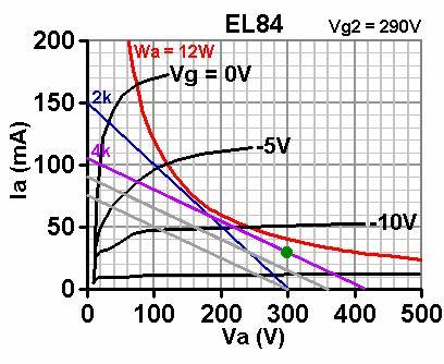
FWIW the following diagram from Merlin's site shows respective 'A' and the 'B' load lines for one half of an EL84 PP stage. The purple line (4k) is the 'A' load line, and the blue line (2k) is the steeper 'B' load line (which shows the halving of load resistance that occurs for the 'on' tube, when the opposite tube goes into cut-off)
[img:408:334]http://www.valvewizard.co.uk/PushpullLoadline2.jpg[/img]
The steeper B load line reflects a condition where more current is drawn through the 'on' tube in this part of the signal cycle, hence you get more power supplied through the OT to the speaker (from the one 'on' tube) during this part of the cycle (which is why Class A/B is more efficient than Class A).
If that makes it any clearer
He who dies with the most tubes... wins
Re: Class A/AB switching
It will, once I focus on it -- thanks -- I basically learned most of what I know from Merlin's site.
Joe
[quote="tubeswell"]FWIW the following diagram from Merlin's site shows respective 'A' and the 'B' load lines for one half of an EL84 PP stage. The purple line (4k) is the 'A' load line, and the blue line (2k) is the steeper 'B' load line (which shows the halving of load resistance that occurs for the 'on' tube, when the opposite tube goes into cut-off)
[img:408:334]http://www.valvewizard.co.uk/PushpullLoadline2.jpg[/img]
The steeper B load line reflects a condition where more current is drawn through the 'on' tube in this part of the signal cycle, hence you get more power supplied through the OT to the speaker (from the one 'on' tube) during this part of the cycle (which is why Class A/B is more efficient than Class A).
If that makes it any clearer[/quote]