Thanks for the note. I posted a PM to Colossal.
Niki
Jim kelly single channel layout ?
Moderators: pompeiisneaks, Colossal
Re: Jim kelly single channel layout ?
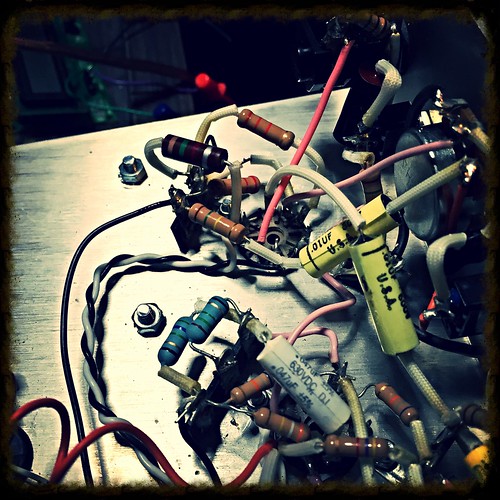
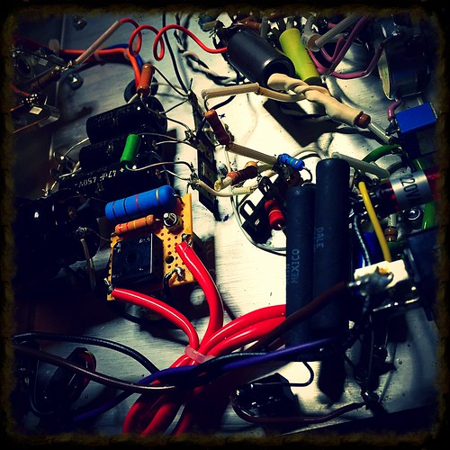
Couple of shots and some rough sounds while still in "design phase". Temporarily soldered components quite evident.
I am waiting for few components to arrive to try few things, prior to post the whole thing in a separate thread, including the schematic and hopefully, at some point - the P2P layout.
But it is the Kelley amp pre (with some changes making it actually closer to Ampeg SB-12 pre) going into Class A, SE poweramp (defeats part of the design goals of the original, but it is becoming quite an interesting amp ). It can use 6V6, 5881, KT77, 6L6GC as a power tube and sounds good and quite different (expected) with all of them. P2P wiring.
[img:500:500]https://farm2.staticflickr.com/1669/263 ... a38850.jpg[/img]
[img:500:500]https://farm2.staticflickr.com/1508/263 ... 6cfbae.jpg[/img]
Sound
https://soundcloud.com/synchu/leftover-something-2
Btw., I verified my build against the layout as kindly made available to me and the layout still seems to be missing the coupling capacitor after V1B.
Niki
I am waiting for few components to arrive to try few things, prior to post the whole thing in a separate thread, including the schematic and hopefully, at some point - the P2P layout.
But it is the Kelley amp pre (with some changes making it actually closer to Ampeg SB-12 pre) going into Class A, SE poweramp (defeats part of the design goals of the original, but it is becoming quite an interesting amp
[img:500:500]https://farm2.staticflickr.com/1669/263 ... a38850.jpg[/img]
[img:500:500]https://farm2.staticflickr.com/1508/263 ... 6cfbae.jpg[/img]
Sound
https://soundcloud.com/synchu/leftover-something-2
Btw., I verified my build against the layout as kindly made available to me and the layout still seems to be missing the coupling capacitor after V1B.
Niki
Re: Jim kelly single channel layout ?
Hi Niki !Synchu wrote:
Btw., I verified my build against the layout as kindly made available to me and the layout still seems to be missing the coupling capacitor after V1B.
Niki
That sound odd to me.
I probably have all the schematic and layout that have been on the web, yes they have all errors or are not complete, but I have never seen that they are missing the coupling capacitor after V1B allways been a 10 n on the plate (220k).
Re: Jim kelly single channel layout ?
No that was not John doing that, Jim use 2X 4K/10W on his later models probably to make the 6V6 tubes to last longer.hbamp wrote:John Suhr changed the shared screen resistor in 2 X 3K9@5W. There must be a good reason for that.
Re: Jim kelly single channel layout ?
Hi Steverenshen1957 wrote:
Hi,
Kevin O'Connor featured the two channel amp in TUT vol 5, but with an updated (Super Stock) Power Supply (different from Kelley's original).
After Suhrs involvement and reissue, the website deleted the two channel amp schematics (with voltages); one as originally built and a later version with LED Bias and modifications to the Gain Channel
As originally built, one channel had a 12AT7 tube and the other had a 12AX7 with the signal diodes. The later version had 12AX7's in both channels, the gain channel had removed the signal diodes.
Kelley's concept was to keep the amp clean and let the power tubes supply the distortion, which was contrary to what MESA and Marshall were doing at the time.
Best regards,
Steve
Well I guess that is my fault that Kevin O'Connor did spend a chapter in TUT5 about Jim Kelly amp, I gave him the schematic I had and info about my experience playing on one.
Yes Kelly did change the two channel amp later on.
Rhythm/clean channel are like u say: 12AT7 to 12AX7 no diodes and the bright cap 470p to 220p.
Lead channel (which had the power attenuator on it)
Kept the diodes but the bypass cap om the cathode went from 20 uF to 2 uF also the slope resistor went from 100K to 220k.
The amp also got a boost cap .0047 on V4A and some minor modes on the reverb, he also change the screen resistor to 2X 4K/10W
Last edited by oj on Wed Apr 13, 2016 2:16 pm, edited 1 time in total.
Re: Jim kelly single channel layout ?
My bad - it is V1A coupling capacitor that was missing.oj wrote:Hi Niki !Synchu wrote:
Btw., I verified my build against the layout as kindly made available to me and the layout still seems to be missing the coupling capacitor after V1B.
Niki
That sound odd to me.
I probably have all the schematic and layout that have been on the web, yes they have all errors or are not complete, but I have never seen that they are missing the coupling capacitor after V1B allways been a 10 n on the plate (220k).
It was the schematic that was available on the jimkelleyamplifiers.com web site (it was deleted, but still available through various internet archives).
Niki
Re: Jim kelly single channel layout ?
Like Forrest Gump sad : Skit happensSynchu wrote:My bad - it is V1A coupling capacitor that was missing.oj wrote:Hi Niki !Synchu wrote:
Btw., I verified my build against the layout as kindly made available to me and the layout still seems to be missing the coupling capacitor after V1B.
Niki
That sound odd to me.
I probably have all the schematic and layout that have been on the web, yes they have all errors or are not complete, but I have never seen that they are missing the coupling capacitor after V1B allways been a 10 n on the plate (220k).
It was the schematic that was available on the jimkelleyamplifiers.com web site (it was deleted, but still available through various internet archives).
Niki
-
dorrisant

- Posts: 2628
- Joined: Tue Sep 21, 2010 1:27 pm
- Location: Somewhere between a river and a cornfield
- Contact:
Re: Jim kelly single channel layout ?
I ran a calculator for the PT current draw... I have a Dynaco 4k3 sitting here.
Did I do something wrong? I wasn't expecting the current draw to be that high.
Anyway, looking for a PT that will work for this.
Did I do something wrong? I wasn't expecting the current draw to be that high.
Anyway, looking for a PT that will work for this.
You do not have the required permissions to view the files attached to this post.
"Education is what you're left with after you have forgotten what you have learned" - Enzo
Re: Jim kelly single channel layout ?
Nothing wrong with your input.
Just the amount of approximation and assumptions taken when calculating the current draw - factor in hugely when there are large deviations from the datasheets.
See the referenced text from Merlin's web site:
"Even without a load line you can estimate the output power for a typical pentode, assuming the load impedance isn't unusually small for the type of valve being used:
P = 2 * (HT-50)^2 / Rload"
That is exactly what I put in the calculator. One of the assumptions that is usually pretty close to the reality - is how low plate voltage can swing - 50V for a typical PP stage, typical pentode/tetrode operation.
Second important one is "load impedance isn't unusually small" - while ~4k is OK for 4 x 6V6 amp - this is at ~300V plate voltage.
At ~450V this does not hold true (assuming I is the same - albeit it will obivously going to be adjusted, if we don't aim for fancy fireworx ).
At the plate voltages of this amp, I would rather go the standard way using load lines to estimate the maximum current draw, starting with 14W max. power dissipation (which is still higher than the datasheet, but as far as I am aware this is the dissipation that JK amp puts out), 4.3K output impedance and plate voltage of ~450V.
In practice, I would expect that a power transformer between 160mA and 200mA should handle current requirements just fine.
Niki
PS. I am hapilly taking any suggestions for improvement of the calculator
Just the amount of approximation and assumptions taken when calculating the current draw - factor in hugely when there are large deviations from the datasheets.
See the referenced text from Merlin's web site:
"Even without a load line you can estimate the output power for a typical pentode, assuming the load impedance isn't unusually small for the type of valve being used:
P = 2 * (HT-50)^2 / Rload"
That is exactly what I put in the calculator. One of the assumptions that is usually pretty close to the reality - is how low plate voltage can swing - 50V for a typical PP stage, typical pentode/tetrode operation.
Second important one is "load impedance isn't unusually small" - while ~4k is OK for 4 x 6V6 amp - this is at ~300V plate voltage.
At ~450V this does not hold true (assuming I is the same - albeit it will obivously going to be adjusted, if we don't aim for fancy fireworx
At the plate voltages of this amp, I would rather go the standard way using load lines to estimate the maximum current draw, starting with 14W max. power dissipation (which is still higher than the datasheet, but as far as I am aware this is the dissipation that JK amp puts out), 4.3K output impedance and plate voltage of ~450V.
In practice, I would expect that a power transformer between 160mA and 200mA should handle current requirements just fine.
Niki
PS. I am hapilly taking any suggestions for improvement of the calculator
-
dorrisant
- Posts: 2628
- Joined: Tue Sep 21, 2010 1:27 pm
- Location: Somewhere between a river and a cornfield
- Contact:
Re: Jim kelly single channel layout ?
Thanks for the explanation Niki, and thanks for the calculator in the first place.
I'm thinking about springing for a 250mA Edcor PT, sounds like it should be adequate then. I have a blank chassis from CEDist that will use. I just can't stop myself from gathering parts... The sickness continues!
I'm thinking about springing for a 250mA Edcor PT, sounds like it should be adequate then. I have a blank chassis from CEDist that will use. I just can't stop myself from gathering parts... The sickness continues!
"Education is what you're left with after you have forgotten what you have learned" - Enzo
Re: Jim kelly single channel layout ?
Tony, KOC in TUT5 called out a Hammond 273BX (201 ma) in his Kelly chapter if that helps.
John
John
-
dorrisant
- Posts: 2628
- Joined: Tue Sep 21, 2010 1:27 pm
- Location: Somewhere between a river and a cornfield
- Contact:
Re: Jim kelly single channel layout ?
Thanks John, I was wondering what he specified for the build... looks like 201mA. No filament tap though. Since I was thinking Edcor and would have to wait for them to build one, I may call and ask if they could add a 60v bias tap to an existing design.John_P_WI wrote:Tony, KOC in TUT5 called out a Hammond 273BX in his Kelly chapter if that helps.
John
Ok... that about does it for the preliminary build questions, I'm gonna build one as close to exact specs as possible. If any of you see anything I might be missing, please let me know. I will post up a new thread here and probably on rj's site at the same time.
"Education is what you're left with after you have forgotten what you have learned" - Enzo
Re: Jim kelly single channel layout ?
I am looking forward to it and will follow on. Definitely in my to-build list to do the full blown amp. While the SE experiment, I did and described above turned a very nice small amp, the PA stage of this one is critical to its acclaimed sound properties.
Btw., I like Edcors very much, would love to get some more, but they cost their weight in gold till come to Europe, so will source something more local...
Niki
Btw., I like Edcors very much, would love to get some more, but they cost their weight in gold till come to Europe, so will source something more local...
Niki
-
dorrisant
- Posts: 2628
- Joined: Tue Sep 21, 2010 1:27 pm
- Location: Somewhere between a river and a cornfield
- Contact:
Re: Jim kelly single channel layout ?
I found and purchased a Stancor P-6314 PT on eBay... shipped cost was about $15 -$20 less than the equivalent rated Edcor and will arrive about 5 weeks earlier.
350-0-350 @200mA
6.3v CT @5.5A
5v @3A
Now I just need to figure out the leads to the Dynaco clone OT again... and order a bunch more parts.
350-0-350 @200mA
6.3v CT @5.5A
5v @3A
Now I just need to figure out the leads to the Dynaco clone OT again... and order a bunch more parts.
"Education is what you're left with after you have forgotten what you have learned" - Enzo
-
fenderbender
- Posts: 21
- Joined: Sun Feb 13, 2011 6:04 pm
- Location: Denver
Re: Jim kelly single channel layout ?
I worked on a friend's Fortune amp (Jim Kelley), that thing had a PT that put about 510V on the anodes on the 6V6's, at 120V line AC. I figured Mr. Kelley used a PT intended for 110VAC. I suggested to my buddy, to get a Variac, so he could lower the voltage a little. At 110VAC it sits at about 475VDC on the plates....
That was the single channel non-reverb version. It sounded really nice with and without pedals in front of it and loud as hell!
Tom
That was the single channel non-reverb version. It sounded really nice with and without pedals in front of it and loud as hell!
Tom
It sounded so sweet... And then it caught fire!