Marshall 9200 as an hi-fi starting kit

General discussion area for tube amps.

Moderators: pompeiisneaks, Colossal

Post Reply
User avatar
roberto
Posts: 1841
Joined: Tue Nov 27, 2007 4:45 pm
Location: Italy

Marshall 9200 as an hi-fi starting kit

Post by roberto »

Dear all,

I've found a very cheap Marshall 9200 that I would like to convert to a PA for my Klipsch.

The idea came looking at its schematic:
http://drtube.com/schematics/marshall/9100-61-02.pdf
http://drtube.com/schematics/marshall/9100-60-02.pdf

Where the PI has that CCS to get better balance. That's something that can be usually found on hi-fi amps more than on guitar or bass amps.

On top of that there's this reading related to a strong IMD improvement:
http://www.diyaudio.com/forums/tubes-va ... ey-46.html
http://www.southampton.ac.uk/~apm3/diya ... matic1.gif
Have a look at what Allen Wright did on this amp: notice that the 0V side of the cathode bypass capacitors do not go directly to 0V. The 2 0V ends of the capacitors are connected together and then have a 68 Ohm resistor to 0V. You can try this on a "Baby Huey". The fact that we use current sources rather than fixed resistors for the cathode biasing will not make any difference to this scheme.

This is a 3rd harmonic distortion suppression scheme and it is worth trying on a "Baby Huey". Try resistor values of between 33 ohms and about 150 ohms (use 2 watt resistors) to see what sounds best. You are listening for a smoother, less "Edgy" sound, particularly at higher frequencies. And of-course, let us know if you think it makes any difference, and if so, what resistor value sounds best to you.
By now the idea is to:
Remove C5 and C7 (presence caps).
Increase the coupling caps to 100n.
Switch the PA to normal mode (feedback is just 100k//330k).
Then see how it sounds.

Next steps will be to remove V1 and V3 and work on it more in depth, also removing the fan and substituing the MPSA43.

Do you guys have other suggestions?
User avatar
roberto
Posts: 1841
Joined: Tue Nov 27, 2007 4:45 pm
Location: Italy

Re: Marshall 9200 as an hi-fi starting kit

Post by roberto »

These are the plots of the PI as I would like to modify it.
You do not have the required permissions to view the files attached to this post.
User avatar
roberto
Posts: 1841
Joined: Tue Nov 27, 2007 4:45 pm
Location: Italy

Re: Marshall 9200 as an hi-fi starting kit

Post by roberto »

Future upgrade would be circuit 15 (the super triode) here described:
http://www.mennovanderveen.nl/nl/downlo ... load_3.pdf

How would this transformer be built?
On the cheaper Edcor and Hammond UL OTs that I have measured, the central B+ to UL winding section(s) is generally well coupled to the secondary for UL purposes. I often see (measuring leakage inductances of the individual primary sections to the secondary, correcting for turns) one of the outer plate to UL sections poorly coupled. A poorly coupled section is best driven by a high impedance pentode plate since the leakage L is automatically compensated for by a current source.

The UL taps are a good place to take voltage feedback from, due to their close coupling to the secondary. +1 for UL mode, but the screens have a non-linear impedance due to the large variation in screen current. -1 for UL.

The usual plate to grid1 "Schade" resistive approach makes for a difficult to drive grid for the driver stage. Going back to the driver grids instead requires cross-coupled neg. feedbacks. This means the feedback(s) has to go thru the OT in class B mode, phase issues. In any case, the assymmetric leakage L's at the plate winding taps make for a poor feedback source, they should come off the UL taps instead.

If you take the feedback resistors back to the driver cathodes, then no more cross-coupling or hard to drive grids. (well the driver grids require more signal, but this is low level already)
The RCA handbook amplifier uses this (plus some Schade). Then taking the resistive feedbacks from the UL taps makes for more accurate coupling to the secondary, and helps attenuate the signal some as well.

On the downside, feedbacks to the driver stage cathodes seem to get poor "sound" reviews. Probably because they work too well to remove the distortion. With pentode drivers, the local loop gain can be phenomenal (no signal thru the OT, ie, no cross coupling in feedbacks, minimal phase issue). Maybe why RCA lightened up on it with partial "Schade", or to soften the saturation/clipping.

So far a standard UL OT will work fine. If you are going to wind your own OT, then I would add a winding with the same number of turns as the UL to UL taps, insulated for ground voltage, and put on as an afterthought (ie, kept out of the way of the closely coupled windings.) Then put caps between its ends and the UL taps. Voila.... closely coupled now. Can use it for a separate UL winding or a CFB winding OR:

Going further yet, The UL sections are the best coupled sections, but we normally use only one of them at a time in class aB. Why not use both at once all the time, a 2X better OT then, since the leakage L is halved. So we go Circlotron/Mac like by connecting the plates to the usual plate taps, and the cathodes to the extra winding ends (opposite UL tap end). Center point of the extra winding is grounded. (no need for two floating B+ like the Circlotron this way) Each tube effectively uses both UL sections and one plate section now. The plate section is operated by a high Z plate, so leakage does not matter there.

For 40% UL taps, this effectively puts 1.4 X turns on each tube from the usual, so the primary Z is doubled. So the entire OT can have its turns dropped by 30% (0.707) to get back to the same primary Z. This all works out to the same number of primary turns as the usual OT (including the extra winding here now). You now have a 1/2 Primary Z OT xformer to wind (as far as the tightly coupled windings are concerned) so expect another 2X bandwidth performance. Total is 4X better now, for no extra total primary turns. Ie, Mac performance with an easy to wind OT. Note that the tubes now have one UL to B+ section (in the added winding actually) acting as CFB, giving 28% CFB (40/(100+40). You can still do the above driver scheme too, or others.

ALL OTs should be wound this way by default. So flexible, can do most anything well.
http://www.diyaudio.com/forums/tubes-va ... post826342
User avatar
roberto
Posts: 1841
Joined: Tue Nov 27, 2007 4:45 pm
Location: Italy

Re: Marshall 9200 as an hi-fi starting kit

Post by roberto »

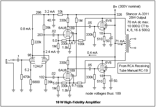
Take a look at this pdf, schematic page 14:
http://www.pmillett.com/file_downloads/RCA_HiFi.pdf


Image
The great advantage of the beam power pentode is that very little drive power is required. In fact, with class AB1 operation, only voltage is required. If we were using power triodes (and these are very popular) considerable power could be necessary to drive the grids. Here, however, the 6V6's are driven by 6AU6 pentodes operating at a very small plate current with large plate resistors, and a grid bias of -1.7 V. The plate voltages are only some 182 V, and the screens are supplied through a 1M resistance, so these tubes are well within their maximum voltage ratings.

This is a feedback amplifier, and the bias for the 6AU6's is not supplied by the small cathode current, but by feedback from the plates of the 6V6's, which holds the cathodes of the 6AU6's at 6.7V. The feedback ratio is about 56, which sets the voltage gain of the amplifier, by the usual rule. A voltage divider, consisting of the 330k and 1M resistors, supplies the grids with the proper bias. The open-loop gain of the 6AU6 stages is about 165, while the gain of the 6V6 output stages is about 15, making a loop gain of 165 x 15 / 56 = 44. The effect of the feedback is to hold the voltage gain at 56 (grid of 6AU6 to plate of 6V6), and to decrease any nonlinearities by a factor of 44. This means that the amplifier is indeed very linear, with constant gain, over a wide frequency band. Feedback is far more effective in achieving linearity than any selection of tubes. Fidelity is not limited by the amplifier; the loudspeaker and signal source are far more limiting, and must be considered in relation to the amplifier, which must compensate for their deficiencies.

Since the feedback network consists of only resistors, the gain will be independent of frequency. This is quite important, since the impedance of a loudspeaker is not constant, but varies with frequency, and the resistance reflected back to the output tubes affects the gain. A triode is a voltage source, with low plate impedance, so its gain is less affected by the load than that of a pentode, which is a current source, as is a transistor. Remember that the gain is gm(rp||RL). The triode gain is dominated by its plate resistance, while the pentode gain is dominated by the load resistance. Triodes were preferred for output stages for this reason, though feedback is a much better and more efficient solution. An output triode should have high transconductance and low plate resistance, which implies a low amplification factor. Compensating networks containing capacitors can also be used to reduce the gain at high frequencies in pentode circuits. The general idea is to make the gain at 1000 Hz equal to the gain at 400 Hz, to ensure rough constancy of gain over the most important frequencies.
http://mysite.du.edu/~etuttle/electron/elect35.htm
User avatar
roberto
Posts: 1841
Joined: Tue Nov 27, 2007 4:45 pm
Location: Italy

Re: Marshall 9200 as an hi-fi starting kit

Post by roberto »

User avatar
roberto
Posts: 1841
Joined: Tue Nov 27, 2007 4:45 pm
Location: Italy

Re: Marshall 9200 as an hi-fi starting kit

Post by roberto »

Were has all the good old people gone on this forum?
User avatar
Phil_S
Posts: 5944
Joined: Tue Oct 23, 2007 10:12 pm
Location: Baltimore, MD

Re: Marshall 9200 as an hi-fi starting kit

Post by Phil_S »

roberto wrote: Thu Feb 23, 2017 7:16 pm Were has all the good old people gone on this forum?
Roberto: This particular thing is not something I can say much about and maybe others here aren't hi-fi people, but, just give it a chance. I'm fairly certain someone who's got the chops to comment will give you something. Remember, TAG is just emerging from the middle ages. It could take a while to recover.
User avatar
roberto
Posts: 1841
Joined: Tue Nov 27, 2007 4:45 pm
Location: Italy

Re: Marshall 9200 as an hi-fi starting kit

Post by roberto »

I'm sorry, what happened?
User avatar
Phil_S
Posts: 5944
Joined: Tue Oct 23, 2007 10:12 pm
Location: Baltimore, MD

Re: Marshall 9200 as an hi-fi starting kit

Post by Phil_S »

TAG had the plague.
User avatar
roberto
Posts: 1841
Joined: Tue Nov 27, 2007 4:45 pm
Location: Italy

Re: Marshall 9200 as an hi-fi starting kit

Post by roberto »

God bless TAG.

Here you can find un update on the topic.
A first mod to improve the headroom and balance of the PI, plus the 2nd to 3rd harmonic content.

This is not for hi-fi, just to use it for its purpose.
You do not have the required permissions to view the files attached to this post.
User avatar
roberto
Posts: 1841
Joined: Tue Nov 27, 2007 4:45 pm
Location: Italy

Re: Marshall 9200 as an hi-fi starting kit

Post by roberto »

Looking at similar configurations, I came into the 9005 poweramp:
http://drtube.com/schematics/marshall/9005.gif

Searching some more informations on that 9005 configuration and its origins, I've found that the Major had a similar configuration, with a concertina plus a differential amp based on a 12au7.

Well, I've also found that the original schematics by Marshall are wrong, because the signal is taken from the cathode of the concertina, and the 1M resistor is also connected to the cathode of the concertina, even if the schematics say the opposite:
http://drtube.com/schematics/marshall/1966u.gif
http://drtube.com/schematics/marshall/1967u.gif
http://drtube.com/schematics/marshall/1978u.gif
Post Reply