5F1 CHAMP SCRATCH BUILD - NEED HELP with 2 PROBLEMS

General discussion area for tube amps.

Moderators: pompeiisneaks, Colossal

t7mackie
Posts: 22
Joined: Sun Jan 10, 2021 4:58 pm

5F1 CHAMP SCRATCH BUILD - NEED HELP with 2 PROBLEMS

Post by t7mackie »

Hello all - 1st post here!! I want to express a very sincere thank you to any and all that take the time to help.

I'll put the TL;DR next with the meat of the matter and after that I'll add additional background.

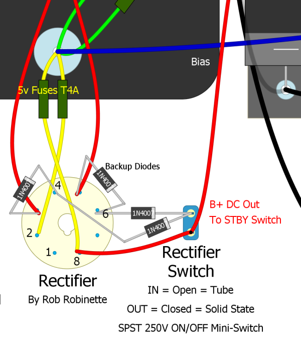
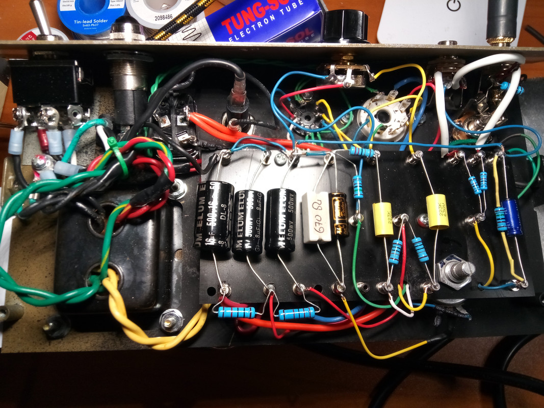
I took a stock Fender Champion 600, gutted it down and reused only the wood cabinet, the power cord, and the metal chassis. I built the entire rest of the amp from ground up. I used the standard 5F1 schematic. All components are the value listed on the 5F1 schemo with power ratings equal to or above. The mods I added are Uncle Doug's variable negative feedback with a 5k resistor and ~48k pot replacing the 22k resistor. That appears to work as designed. I also did Rob Robinette's selectable solid state / tube rectification mod - this also appears to work as designed and has no effect on the problems I'm having.

2 problems I'm having:

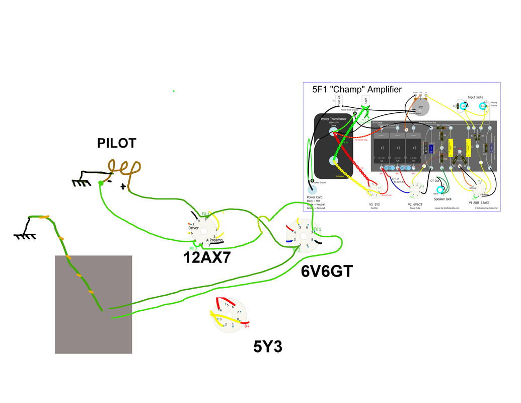
1) Pilot light turns on for about 30 seconds then burns out. I tried searching the web for pilot light wiring info but it seems the pilot light is more of an afterthought in these regards. I attached a picture of exactly how I have it wired.
- does it matter that the pilot is last in the run? It's wired 1st in every schematic I've seen.
- does it matter that the schematic has the wire from 6V6 pin 7 to 12AX7 pin 9 but I have pin 7 to pin 4 & vice versa with the other 6.3 wire (see my picture)?
- the negative lug on my pilot light is bonded to the metal body of the pilot light housing which then becomes a chassis ground - is this right / normal?

I measure 6.5 volts A/C on the 2 green 6.3 volt wires. When I mount the pilot light holder to the chassis and measure the base (+) and the chassis body (which is bonded to ground because it's made of metal) I measure 3.0 volts A/C.

2) The amp sounds really good except when I turn the volume up, after almost exactly half way up it seems it breaches some threshold and the guitar signal immediately then gets very weak and the amp starts to distort really badly. It's not a nice gradual rise in good tube breakup as I turn the volume up - the sound is nice and clean until half way up and then higher than that certain threshold it's like a switch if flipped and it just sounds like crap above that.

Any suggestions on where to look for problems? I will gladly supply photos or multimeter readings.


--BACKGROUND--

This is my 1st amp build. I did do a few years of commercial / industrial electrical work in the past and I have also built about a dozen or so guitar effects pedals recently. I did take electronics in tech school but that was a million years ago. I have a fundamental understanding of electronics but I'm more of a tech / parts-changer as opposed to being an engineer.

When I first finished this build the pilot light hadn't been delivered yet so I wired all the tubes leaving a taped up pair of green wires for the pilot. Everything seemed to work perfectly. The bias was a little hot at 115% over the 12 watt max.

When I received the pilot light I installed that as well as changed the cathode bias resistor to bring the bias down to around 95% (on paper). After that it hasn't seemed to work right since. The pilot lights don't last more than 30 seconds and with the volume above half way I lose guitar signal and get awful distortion. Turning the volume knob up the amp sounds great until I get to one specific spot and it just farts out above that spot. I never had turned the volume about 7 or 8 even before I made the changes so I don't know if it always had this problem but that threshold was above 7/8 and I never reached it. I haven't measured the new bias and I haven't energized the circuit after blowing up the 2nd pilot light because I wanted to run this by the amp building community first to get your thoughts, opinions and advise.

Any help & guidance is greatly appreciated!!

Image
Image
User avatar
xtian
Posts: 7019
Joined: Mon Apr 19, 2010 8:15 pm
Location: NorCal
Contact:

Re: 5F1 CHAMP SCRATCH BUILD - NEED HELP with 2 PROBLEMS

Post by xtian »

Welcome!

No, the pilot lamp cannot be grounded. This has created a short from the heater string to ground. Amazing if you haven't burned something up. Even after the pilot lamp burns open, or if no lamp is installed, you have one leg of your heater coil directly connected to ground, which is bad.

Issue #2 is probably directly related.
I build and repair tube amps. http://amps.monkeymatic.com
User avatar
martin manning
Posts: 13258
Joined: Sun Jul 06, 2008 12:43 am
Location: 39°06' N 84°30' W

Re: 5F1 CHAMP SCRATCH BUILD - NEED HELP with 2 PROBLEMS

Post by martin manning »

I can see how running the heaters at half-voltage would result in very low emission and distorted sound, but I don't see how half-voltage would burn out the pilot lamp, or how a direct short on half of the heater winding wouldn't start producing smoke very quickly. You could disconnect the green/yellow center tap ground (allowing the pilot lamp holder to be the ground reference) and see if things straighten up. Start with tubes and pilot lamp removed, and check for normal voltages. You can try this while you're seeking an un-grounded pilot lamp holder.
Last edited by martin manning on Sat Jan 16, 2021 7:42 pm, edited 1 time in total.
Stevem
Posts: 4593
Joined: Fri Jan 24, 2014 3:01 pm
Location: 1/3rd the way out one of the arms of the Milkyway.

Re: 5F1 CHAMP SCRATCH BUILD - NEED HELP with 2 PROBLEMS

Post by Stevem »

Champs and Harvard amps do have transformers whose 6.3 volt heaters have no center tap, as in no yellow/green wire.

One wire of the PT's heater tap goes to ground then the other wire goes to the pilot light to which the tube heaters (other then the rectifier) get fed from and each tube and the pilot lamp goes to ground.

The best thing you can do with these amps to lower 60 hz hum levels is wire the heaters as if the PT had a center tap, and then off of the pilot lamp make a artificial center tap to ground with two 1 watt 100 ohm resistors.
When I die, I want to go like my Grandfather did, peacefully in his sleep.
Not screaming like the passengers in his car!😊

Cutting out a man's tongue does not mean he’s a liar, but it does show that you fear the truth he might speak about you!
t7mackie
Posts: 22
Joined: Sun Jan 10, 2021 4:58 pm

Re: 5F1 CHAMP SCRATCH BUILD - NEED HELP with 2 PROBLEMS

Post by t7mackie »

Thank you everyone for your help.

Why is the metal body of the pilot light bonded to the negative leg??? Usually these are installed into metal circuit chassis. Something is fishy here. Maybe I have a bad light socket?

***OK, I just tested the socket removed from the amp chassis for continuity from the negative leg to the body of the holder and there's no connection. I think I'm losing my mind! It must've been shorting somehow.

The transformer has a 6.3v center tap / green/yellow wire if that makes a difference.

Regardless, I did remove the light from the circuit and taped off the end of the 6.3v wire run but I still have the lowering of signal & bad distortion when the volume is over 50%. I think the two issues are separate problems.

This was my 1st amp build and in doing it I learned what I did not know. Now that I know what I did not know (??) I'm going to strip it all down and rebuild the entire thing from the ground up. Neater, cleaner and hopefully problem free.

Thanks again everyone!

-mac
t7mackie
Posts: 22
Joined: Sun Jan 10, 2021 4:58 pm

Re: 5F1 CHAMP SCRATCH BUILD - NEED HELP with 2 PROBLEMS

Post by t7mackie »

I was just thinking about this in the shower... Of course the lamp holder has continuity to ground, the power transformer has a green/yellow 6.3v center tap bonded to the chassis. That's why I'm not detecting it when the lamp holder is removed.

I think my two problems are related. I'm thinking some B+ voltage is leaking to ground via a short somewhere and it's back feeding up the 6.3v center tap.

If the tube heaters are receiving too much voltage will that translate through the cathode and cause havoc?

Hopefully this all sorts itself out when I rebuild this project from the ground up.
User avatar
Phil_S
Posts: 5954
Joined: Tue Oct 23, 2007 10:12 pm
Location: Baltimore, MD

Re: 5F1 CHAMP SCRATCH BUILD - NEED HELP with 2 PROBLEMS

Post by Phil_S »

I think we may need to see a photo of your pilot lamp to understand what you are dealing with. Here is one that I'd say is typical of what we use. https://www.parts-express.com/Red-Jewel ... D9EALw_wcB

There is a metal head portion that goes through the chassis and is attached with a washer and hex nut. Technically speaking, I think we can agree that it is making contact with the chassis. However, there should be no continuity to the lamp assembly. There are two lugs at the back end that are meant to accept a parallel connection to the 6.3V supply without any ground reference.
Stevem
Posts: 4593
Joined: Fri Jan 24, 2014 3:01 pm
Location: 1/3rd the way out one of the arms of the Milkyway.

Re: 5F1 CHAMP SCRATCH BUILD - NEED HELP with 2 PROBLEMS

Post by Stevem »

Sorry, I did not look close enough to see that you do have a green and yellow filament center tap that gets grounded,
When I die, I want to go like my Grandfather did, peacefully in his sleep.
Not screaming like the passengers in his car!😊

Cutting out a man's tongue does not mean he’s a liar, but it does show that you fear the truth he might speak about you!
t7mackie
Posts: 22
Joined: Sun Jan 10, 2021 4:58 pm

Re: 5F1 CHAMP SCRATCH BUILD - NEED HELP with 2 PROBLEMS

Post by t7mackie »

OK ampaholics. Version 2.0 is finished. I built another Champ from the ground up leaner and meaner.

The pilot light sorted itself out. BUT, I'm getting the same exact problem when turning the volume knob past 5. The amp sounds fantastic under 5. Selectable tube rectification and adjustable negative feedback mods work as intended and don't affect the problem.

Even when not playing anything (which seems to make sense for a class A amp) when I turn the volume knob up to and above one certain point, around 40-50% up, there's a noticeable change in the white noise coming from the speaker and if I play anything with the volume at or above that point it sounds like the speaker is on fire and the capacitors are melting.

I added a 1k 5watt pot in series with the 670 ohm bias resistor to fine tune the bias and it's currently sitting at 11.5 watts of dissipation. It was at 13.5 before I added the pot with the 670R 5w ceramic bias resistor. Absolutely no change to the problem before & after.

I've checked and re-checked the wiring and it seems to be correct. I swapped out the 12AX7 for another I had - no difference. I will try swapping the 6V6GT. The one I'm using is a 50 year old Magnavox (Sylvania?) I salvaged from an old radio out of my landlord's junk pile. Physically it appears to be in new condition but, yeah, probably a gimmie here.

???!???!!!

670 Ohm bias resistor + 130 ohms pot = 800 ohms bias resistance
23 voltage drop
402 plate voltage
.0288 plate current
11.5 watts dissipation (tube rectification)

B+ 414 volts tube rec // 428 volts solid state rec
B++ 376 volts tube red // 388 volts solid state rec

Does that symptom sound like anything to anyone? Any suggestions where to test / check / etc?

Thanks to everyone for their continued support and assistance.

-mac

::EDIT:: The only reused components from build 1 to build 2 are the transformers, pilot lamp holder, tubes and the on / off switch.
sluckey
Posts: 3092
Joined: Sun Jul 22, 2007 7:48 pm
Location: Mobile, AL
Contact:

Re: 5F1 CHAMP SCRATCH BUILD - NEED HELP with 2 PROBLEMS

Post by sluckey »

t7mackie wrote: Wed Jan 27, 2021 2:06 am it sounds like the speaker is on fire and the capacitors are melting.
I bet no one knows what that sounds like! What happens if you disconnect the NFB wire from the OT?
t7mackie
Posts: 22
Joined: Sun Jan 10, 2021 4:58 pm

Re: 5F1 CHAMP SCRATCH BUILD - NEED HELP with 2 PROBLEMS

Post by t7mackie »

Sluckey, I can certainly try that but I was messing with the amp some more tonight and that, "point" on the volume knob stays in exactly the same spot regardless of where I adjust the NFB or if using tube rec or SS. NFB can be adjusted anywhere from 4.7k to 55k.

I set the volume knob to just before the bad point, changed NFB from one extreme to the other and also switched between tube rec and SS and the "spot" was still in the exact same spot. I can hear the change in white noise output when I reach the spot even when not playing the guitar through it.

The plot thickens... I replaced the 6V6GT with a brand new Tung-sol tonight. With the ancient Magnavox tube installed the 'point' on the volume was at around 4 (out of 12) on the knob. Now with the new tube I can turn it up to 7 before it gets messy. Hmmm...

Could there be some oscillation? Should I increase (or decrease) the plate resistors? Grid leak?

I measured the approximate resistance from the sweeper to the input leg on the 1M volume pot (still in the circuit). 0 volume = 900k. The 'point' with the old tube was ~830k. The 'point' with the new tube is ~730k. So any resistance through the volume knob less than ~730k and the signal gets all batty. This means something... I just don't know enough to know what that something is.

Any predictions or recommendations for experimenting with the plate resistors or the grid leak resistor? I'm just guessing though at this point.

The only things in common between my 1st & 2nd builds at this point are the transformers and the circuit itself.


Image

The 1k 5W pot under the 68k's is in series with the ceramic bias resistor. The green wire going to R6 is not a heater, it's coming from a ~47k pot in series with a 4.7k resistor under the board for the adjustable NFB. The 2nd switch is for the tube / ss rectification. All wire is 18ga solid except for the B+ which is 16ga stranded. Rec tube hidden under the board - no tube socket connectors are touching / shorting anything. I used some super duper home depot 18-5 cable that, unfortunately, did not include black. Blue ground wires for the "Euro" look.
sluckey
Posts: 3092
Joined: Sun Jul 22, 2007 7:48 pm
Location: Mobile, AL
Contact:

Re: 5F1 CHAMP SCRATCH BUILD - NEED HELP with 2 PROBLEMS

Post by sluckey »

Sluckey, I can certainly try that but
My suggestion is not to just vary the amount of NFB, but to completely disconnect it. There's a 50/50 chance that the phase is wrong and causing oscillations or other bad sounds/behavior. Just disconnect the wire. If it improves the sound then bingo. If the sound gets worse, just put the wire back.
Stevem
Posts: 4593
Joined: Fri Jan 24, 2014 3:01 pm
Location: 1/3rd the way out one of the arms of the Milkyway.

Re: 5F1 CHAMP SCRATCH BUILD - NEED HELP with 2 PROBLEMS

Post by Stevem »

If it gets worse then also try swapping the OT power input and plate wires.
If the amp then screams out like you set it on fire then the way it was wired is correct.

Also here's a question, does your voltmeter have a setting to test for frequency?
If so we can better help you to determine what's going on in there!

Also lets get the darn basic amp working right before stuffing in any mods, yes?
When I die, I want to go like my Grandfather did, peacefully in his sleep.
Not screaming like the passengers in his car!😊

Cutting out a man's tongue does not mean he’s a liar, but it does show that you fear the truth he might speak about you!
sluckey
Posts: 3092
Joined: Sun Jul 22, 2007 7:48 pm
Location: Mobile, AL
Contact:

Re: 5F1 CHAMP SCRATCH BUILD - NEED HELP with 2 PROBLEMS

Post by sluckey »

Stevem wrote: Thu Jan 28, 2021 11:29 am If it gets worse then also try swapping the OT power input and plate wires.
No. If the sound improves with the NFB disconnected, you would swap the OT leads.
t7mackie
Posts: 22
Joined: Sun Jan 10, 2021 4:58 pm

Re: 5F1 CHAMP SCRATCH BUILD - NEED HELP with 2 PROBLEMS

Post by t7mackie »

Great stuff! Thank you. Now I know what I'm doing today.


I've been looking into big boy multimeters so Hz will be on the checklist.

Thanks, all!

-mac
Post Reply