Hi folks,
This is my first post here at the amp garage, what a great community. I have years of experience with fixing all kinds of musical electronics so I guess I can be also help here at the forums.
Since there's very sparse info on these VHT Pitbull amps, not even mentioning elusive schematic, I thought somebody could help me.
I'm working on a VHT Pitbull 45 combo amp right now and found that one of the higher watt resistors in the power supply / power amp section is blown open, likely from the accident which happened to the V1. It got cracked glass at the base and,the vacuum is gone, white stuff inside, you know the story..... So basically whole preamp section is without juice because of that it seems. No shorts found ....
Anyway, the resistor in question seems like 3W, and is marked as R132, unfortunately the color code is gone, discolored. The neighboring resistor R131 is 10k. Is R132 also 10k?
BTW it comes to me that this amp is a tube eater. Somehow several tubes crack at the base while plugged in to the tube sockets, these sockets seem to be very tough on tubes. No matter how careful you are. Doesn't happen on other amps.
Thanks
ddt
VHT Pitbull 45 Blown Resistor
Moderators: pompeiisneaks, Colossal
VHT Pitbull 45 Blown Resistor
You do not have the required permissions to view the files attached to this post.
-
Stevem
- Posts: 4585
- Joined: Fri Jan 24, 2014 3:01 pm
- Location: 1/3rd the way out one of the arms of the Milkyway.
Re: VHT Pitbull 45 Blown Resistor
There’s no way to tell what it’s value should be so you will need find a schematic or get in touch with VHT or someone who has this model amp to confirm its value.
Next , amps are not hard on tubes in terms of blowing or cracking them open unless the filiment supply is outputting too much voltage.
Before you even replace that resistor I would put in another tube and test to see just where the filiment voltage level is at.
If this amp runs the preamp tubes on DC then the voltage could be way high !
This can run the preamp tubes so hot that they heat up and so fast and the internals over expand with result of splitting the glass with little usage.
Also if there is higher then normal filiment voltage the gain structure of the amp will be way too high!
When I die, I want to go like my Grandfather did, peacefully in his sleep.
Not screaming like the passengers in his car!
Cutting out a man's tongue does not mean he’s a liar, but it does show that you fear the truth he might speak about you!
Not screaming like the passengers in his car!

Cutting out a man's tongue does not mean he’s a liar, but it does show that you fear the truth he might speak about you!
Re: VHT Pitbull 45 Blown Resistor
Ok, let me explain the issue with glass cracking more precisely. It's the physical socket which is causing cracking I believe, likely the contacts are too tight. But also very good point with the heater voltage, I'll check the voltage on 4+5+9 pins to see if we're in the ballpark.
The resistor I am looking for the value of is in the plate circuit of the preamp tubes (HT), there's no voltage on any of the plates of all preamp tubes. Knowing how these power supplies are designed, it is most likely this resistor which didn't survive excessive current. The big electrolytic capacitor behind the resistor also doesn't have any voltage on it, so I believe it's clear.
And yes, I'm looking for a good soul who would take a picture of the internal PCBs of the VHT Pitbull 45 combo and share it here, or just go through the pictures taken previously and identify the value for me. Please!
Thank you

Re: VHT Pitbull 45 Blown Resistor
hello, the two pics i found show that value at 4700 ohms , cheers
https://reverb.com/item/25153990-vht-pi ... uitar-head
http://diyfactory.ru/forum/uploads/img- ... 1af1dd.jpg
https://reverb.com/item/25153990-vht-pi ... uitar-head
http://diyfactory.ru/forum/uploads/img- ... 1af1dd.jpg
Live , Love , Learn
Re: VHT Pitbull 45 Blown Resistor
Thank you y lumox0013, unfortunately these pictures show VHT Pitbull 45 head, I'm working on combo, they look different inside per my understanding. Though they are similar.
Re: VHT Pitbull 45 Blown Resistor
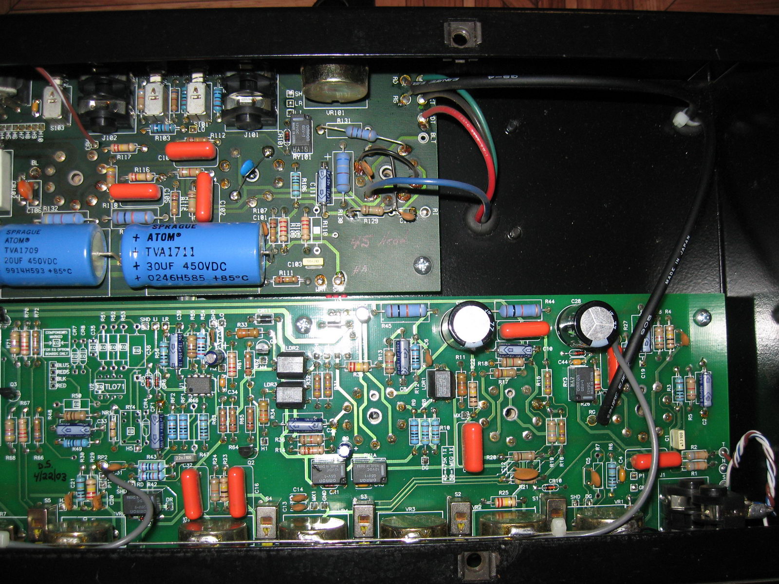
Here's the peek into the VHT Pitbull 45 Combo's guts, with the blown resistor pointed by the red arrow. The boards are further from each other here than in the head. I found only one photo of this amp on a web page of a service in Philadephia, PA. Unfortunately the color code isn't clearly seen there. What do you see in the position of R133, 10k or 1k? Omg just realized that it's some other revision of the PCB to make things easier for everyone, there's a different numbering, lol!
https://64.media.tumblr.com/72cc5723a8d ... e9a153.jpg
https://64.media.tumblr.com/72cc5723a8d ... e9a153.jpg
You do not have the required permissions to view the files attached to this post.
Re: VHT Pitbull 45 Blown Resistor
The image here https://atomiumamps.tumblr.com/post/19 ... ime-for-me appears to show another 10K. I wouldn’t bet my life on it, but that’s what it looks like to me. And you’re right, it’s hard to distinguish between red and orange. It just looks like they both have the same colors.
You do not have the required permissions to view the files attached to this post.

Re: VHT Pitbull 45 Blown Resistor
IIRC PSU resistors are 10k, but my memory could fail.
Concerning the cracked tube, it depends ojn mechanical stress induced by the speaker to the cabinet and so to the pcb.
Concerning the cracked tube, it depends ojn mechanical stress induced by the speaker to the cabinet and so to the pcb.
-
Stevem
- Posts: 4585
- Joined: Fri Jan 24, 2014 3:01 pm
- Location: 1/3rd the way out one of the arms of the Milkyway.
Re: VHT Pitbull 45 Blown Resistor
Well you will not harm anything if it feeds the preamp plates by installing a 15k resistor for now just to get the whole amp up and running to see if any other problems are going on.
When I die, I want to go like my Grandfather did, peacefully in his sleep.
Not screaming like the passengers in his car!
Cutting out a man's tongue does not mean he’s a liar, but it does show that you fear the truth he might speak about you!
Not screaming like the passengers in his car!
Cutting out a man's tongue does not mean he’s a liar, but it does show that you fear the truth he might speak about you!
Re: VHT Pitbull 45 Blown Resistor
On a philosophical level, the actual resistance isn't too important for the dropping resistors in the tubes before the phase inverter.
It helps to ask yourself "why are those resistors there, anyway?" There are two reasonable guesses for that. They could be to drop the plate supply voltage for some esoteric reasons, but it's more likely that they are purely to isolate and filter the B+ for each tube section. The input tube on a guitar amp really, really needs filtered B+ because single ended tube stages have essentially no power supply rejection. Any noise on B+ passes through to the plate. The long string of series-resistor-shunt-cap filtering ending up at the input tube provides the most filtering of any power supply ripple, and any wiggling on the high voltage caused by the power amp sucking current from the first filter cap gets attenuated dramatically.
That last is important for the second reason for a resistor-cap filter - isolation. With stages later in the audio chain pulling current, the power supply voltage gets yanked around. The chain of R-C filters keeps this from getting backwards into more sensitive stages where it can cause motorboating or other oscillation.
A 10K-10uF dropping/filter between stages is pretty effective. The impedance of a 10uF cap at 120Hz is 132 ohms if I hit the right calculator buttons. The attenuation at 120hz is 132/10132 = 0.0132, or about -37db. Of course, that attenuation doubles for every doubling of frequency, so it's very effective as frequency goes up. It doubles if you double the resistor, and halves if you halve the resistor. So in the range of a few k ohms up to a few tens of k ohms, the actual resistor doesn't matter much - it's still really good filtering.
Re: VHT Pitbull 45 Blown Resistor
A couple questions for the OP.
1. What is the preamp tube complement? I dug up a Fryette guide that said it had (4) 12AX7’s and (1) 12AT7. Is that what your amp has?
2. What is the difference in preamp tube complement between the combo and the head version of this amp?
1. What is the preamp tube complement? I dug up a Fryette guide that said it had (4) 12AX7’s and (1) 12AT7. Is that what your amp has?
2. What is the difference in preamp tube complement between the combo and the head version of this amp?
Re: VHT Pitbull 45 Blown Resistor
This particular combo amp has the below tube line up, according to http://www.fryette.com/content/45_SP30R2.pdf .
There is EL84 in the place of reverb driver here in this amp.
TUBE FUNCTION AND LOCATION CHART
Each 12AX7 has two sections/functions. Section A is shown first, Section B is second. Factory
recommended tubes are listed under each location. Numbering sequence is right to left looking at
back of amp starting with the row closest to front panel of amp.
V1 (shielded tube) Reverb return amplifier.
12AX7WB Russia Input Gain Stage 1 and signal splitter for both channels
V2 Tone Control Driver, Drive channel
12AX7 China Gain Stage 3 for Drive channel
V3 Gain Stage 2 for Clean channel
12AX7 China Gain Stage 2 for Drive channel
V4 Reverb Driver.
12AT7 Not interchangeable with 12AX7, EF86 or EL84!!!
1995-1999 uses EL84
2001-2004 uses EF86
V5 Phase Inverter
12AX7 China Power amp input stage
V6-9 Power Tubes
EL84 Russia
V10 Rectifier Tube Forty-Five models only.
5AR4
Re: VHT Pitbull 45 Blown Resistor
Ok, this is all just guess work since we don't have a schematic or typical voltages for this amp. If all four 12AX7s and the EL84 reverb driver are "downstream" from this voltage dropping resistor, then that's quite a lot of current. I have no idea what the exact bias points would be, but let's estimate 2.5mA for each 12AX7 and 30mA for the EL84 (???). That would be a total of 40mA for the preamp section. If that first resistor is a 10K, then it will drop 400V which seems a bit high eh?  If it's a 1K resistor, then it's dropping 40V and that sounds more reasonable. I assume the reverb driver current would then split off at that node, so the remaining 10mA for the 12AX7s passes through the 10K resistor that follows. That would drop 100V which seems like a lot, but not if the reverb driver is getting 300V or more.
In my previous post, it was hard to tell if that 3rd stripe was orange or red. And maybe it is orange, because who really knows how this preamp is supplied, but if it supplies power to the EL84 first, I would guess it was red stripe and that's a 1K dropping resistor.
Like I said before, I wouldn't bet my life on it, but we are working with limited data here.
Re: VHT Pitbull 45 Blown Resistor
... and if one of the resistors in the string burned up, it's likely the next shunt capacitor in the string shorted.
Re: VHT Pitbull 45 Blown Resistor
UPDATE: I popped the resistor 10k/3W in and the amp is back in service and kicking. No shorts found anywhere before, the power supply caps are actually also new, F&Ts and ICs from Tube Depot. Heater voltage is 12V DC, filaments are in series here, so there's always 6V between the pins 4 & 9 or 5 & 9, or 12V between 4 & 5.
I've had this amp in service before, replacing broken impedance switch and noticed this resistor's discoloration too, but it was working back then. It really looks like the V1 accident likely caused it to burn open.
I've had this amp in service before, replacing broken impedance switch and noticed this resistor's discoloration too, but it was working back then. It really looks like the V1 accident likely caused it to burn open.