Hello.
I'm trying to build a Diezel VH4 clone.
I said clone, but it's not a grand job.
I think I will work by omitting or simplifying many parts.
I need to configure channel switching, but I don't have electrical knowledge, so it's difficult to create or apply a new circuit myself.
Basically, the channel switching configuration of this amplifier is :
One DPDT relay is assigned to each channel.
To operate a specific channel, turn on only the relay assigned to that channel and turn off all other relays.
Among the latching circuits I know, I remember the circuit of Soldano X88R.
The circuit diagram is shown below.
As you know, the X88R is a three-channel amplifier. So this switching circuit is also composed of 3 channels.
However, when I looked at the configuration of the IC, I thought that it would be possible to implement a 4-channel circuit by applying this circuit, seeing that there are 4 channels.
However, when I tried it, it was impossible to configure the reset logic for 4 channels because the CD4081 has only 2 input tabs.
Are there any other examples of latching circuits I need?
"Total 4 channels, when selecting 1 channel, other channels are off"
Since I don't have any electrical knowledge, I want to solve it with a really simple circuit.
From my point of view, it would be best to apply the X88R switching circuit to solve it.
If there are other circuits that are as simple as that, I'd be happy if you could recommend them to me.
For your reference, I'm sharing a schematic of the configuration I'm trying to build.
Thank you!
Is there any simple 4 channel Latching Circuit?
Moderators: pompeiisneaks, Colossal
-
psychepool
- Posts: 260
- Joined: Fri Apr 18, 2014 8:29 am
Is there any simple 4 channel Latching Circuit?
You do not have the required permissions to view the files attached to this post.
-
Stevem
- Posts: 4579
- Joined: Fri Jan 24, 2014 3:01 pm
- Location: 1/3rd the way out one of the arms of the Milkyway.
1 others liked this
Re: Is there any simple 4 channel Latching Circuit?
Go to the Londonpower site and pick up one of there switching kits that meet your needs.
You do not have the required permissions to view the files attached to this post.
When I die, I want to go like my Grandfather did, peacefully in his sleep.
Not screaming like the passengers in his car!
Cutting out a man's tongue does not mean he’s a liar, but it does show that you fear the truth he might speak about you!
Not screaming like the passengers in his car!

Cutting out a man's tongue does not mean he’s a liar, but it does show that you fear the truth he might speak about you!
Re: Is there any simple 4 channel Latching Circuit?
There are a number of circuits for discrete switching circuits at geofex.com. Google "geofex.com switching" for a quick list. The link http://www.geofex.com/article_folders/f ... witchr.htm contains a circuit for a two-IC one-of-six switcher logic. It needs only transistor drivers to run higher voltage relays. There are other articles that show other techniques that could be adapted.
That being said, I would advise using a PIC microcontroller. These are cheaper than a single one of the multiple ICs you'd need for a four-switch "radio button" style discrete switcher. They are so cheap that the answer to future proofing the amp against microcontroller failure is to program half a dozen of them and put the spares inside the amp enclosure waiting for a future repair. The commentary on the London Power blurb about being able to repair in the future because it is discrete is at least misquided if not flatly wrong. Discrete logic will still be around decades in the future, but will almost certainly not be available in the DIP package. Non-SMD packages of all kinds are being dropped by semiconductor makers, so even if the logic function is available on the market, a compatible IC package may not be. It may and probably won't be as simple as clipping out an IC and soldering a new one into the holes. Ready spare units is the viable alternative.
I'm dithering about whether to just volunteer to write the code for you. Great Cow Basic lets you program PICs in BASIC, removing the steep assembly learning curve. If I remember correctly, I have some one-of-N BASIC code in the archives.
Re: Is there any simple 4 channel Latching Circuit?
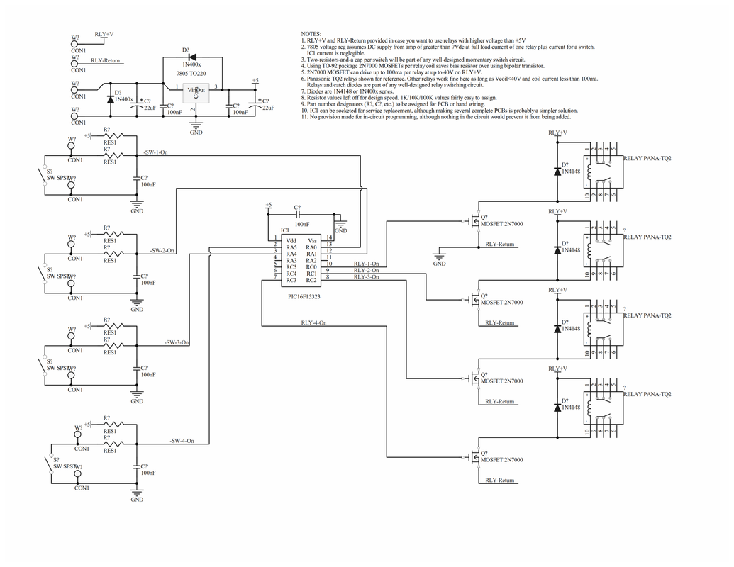
Here's a quick circuit at the bottom.
The switch resistors and caps and the relay driver transistors and diodes, as well as the voltage reg would probably be part of any similar circuit, discrete logic or uC. The single PIC replaces everything else.
The code runs like this. I un-translated it from the previous working BASIC down to human-style pseudocode.
====
Specify the chip and any particulars about the chip to the compiler.
Declare the input pins as causing interrupts on any change in logic level
Declare the variables you'll use, by name and type.
Declare the interrupt routine location/label name.
Enable Interrupts.
MAIN_LOOP:
Did the "changed input" flag get set?
Yes: go to UPDATE_THE_OUTPUTS
No: go to MAIN_LOOP
UPDATE_THE_OUTPUTS:
read the new_input_state variable left from the interrupt routine
Set the outputs to reflect the new condition
re-set the "changed input" flag to zero
go to MAIN_LOOP
INTERRUPT_ROUTINE: (arrives here with interrupts disabled)
read the input pins
run software debounce process to eliminate switch bounces
If debounce shows new input switch is OK then
update the new desired output pins state to match the new switch setting
set the "changed input" flag to high (remembers that there's a new condition)
enable interrupts again
go to MAIN_LOOP
else if debounce says there's no new input switch made
(leave the "changed input" flag alone)
enable interrupts again
to to MAIN_LOOP
====
Re: Is there any simple 4 channel Latching Circuit?
Headfirst amplification sells a MIDI 4X4 board that is setup for 4 channel operation and has the benefit of utilizing the MIDI as well if desired. Using MIDI is not necessary though
https://headfirstamplification.com/pcbs-for-diy
scroll down to the Midi switcher. It's $25 for the board and another $20 or so in parts from Mouser
I've used this board to add MIDI to the preamps I build successfully
Keep in mind any latching switches will need to be swapped with momentary switches to work with this board
Todd
-
psychepool
- Posts: 260
- Joined: Fri Apr 18, 2014 8:29 am
Re: Is there any simple 4 channel Latching Circuit?
Thanks for the good answers.
It took me a while to understand the text because I lacked electricity-related knowledge and English reading skills.
(Actually, I still don't understand the content.)
The first thing I want to say is that the dimensions of the amplifier I want to make are fixed.
I know that there is no advantage or meaning, but DIY is just a hobby anyway, and I want you to accept this part as my own fun factor.
I'm thinking of making it in this shape and size. The chassis size is approximately 310mm x 160mm, which is a compact size.
That's why that pcb shouldn't be too big. This is because space is tight even if only the main circuit of the amplifier is included.
In that sense, londonpower's switching kits are probably difficult to use.
I've also found Headfirst's products while searching for VH4 data, but it seems that manuals such as pcb size are provided only after purchasing the product, so I'm not sure if it can be mounted on the amplifier I'm planning to make.
Could I get a manual for this product? It says "Please see the Documentation page for more info..." but I don't know where to check the documentation.
It is satisfactory that even the mute circuit is included, but it looks like a formidable size when looking at the PCB image.
If the layout is well packed in perfboard, I think it will be possible to make it in the board size I want to make. I'll buy some ICs and do a simple test.
Do you store and use the code you mentioned in the IC called PIC16F15323 shown in the circuit diagram?
I don't know how to write code, and I don't even know how to input into an IC, so how should I work?
Let me ask you one last question.
Is there any way to use the circuit of the Soldano X88R that I have attached to the text as it is?
The Reset Logic IC currently has 2 inputs in 4 circuits, but if it is replaced with an IC with 3 inputs, it seems that it can be made into 4 channels right away.
Is there any AND Gate IC with 3 inputs and 4 circuits to replace the CD4081?
At least, I understand the theory and the size is suitable, so I ask a question because it seems to be the most convenient way for me to approach.
(I was able to understand at least because I was able to find a webpage on the web that explained it in my native language.)
It took me a while to understand the text because I lacked electricity-related knowledge and English reading skills.
(Actually, I still don't understand the content.)
The first thing I want to say is that the dimensions of the amplifier I want to make are fixed.
I know that there is no advantage or meaning, but DIY is just a hobby anyway, and I want you to accept this part as my own fun factor.
I'm thinking of making it in this shape and size. The chassis size is approximately 310mm x 160mm, which is a compact size.
That's why that pcb shouldn't be too big. This is because space is tight even if only the main circuit of the amplifier is included.
In that sense, londonpower's switching kits are probably difficult to use.
I've also found Headfirst's products while searching for VH4 data, but it seems that manuals such as pcb size are provided only after purchasing the product, so I'm not sure if it can be mounted on the amplifier I'm planning to make.
Could I get a manual for this product? It says "Please see the Documentation page for more info..." but I don't know where to check the documentation.
It is satisfactory that even the mute circuit is included, but it looks like a formidable size when looking at the PCB image.
I read the contents of the link. In fact, the principle is not completely understood, but should I know that if I build it according to the circuit diagram using the CD4049, 74C373 and Mosfet as shown in the circuit diagram, it works without problems?R.G. wrote: ↑Wed Jun 07, 2023 2:12 pm There are a number of circuits for discrete switching circuits at geofex.com. Google "geofex.com switching" for a quick list. The link http://www.geofex.com/article_folders/f ... witchr.htm contains a circuit for a two-IC one-of-six switcher logic. It needs only transistor drivers to run higher voltage relays. There are other articles that show other techniques that could be adapted.
......
If the layout is well packed in perfboard, I think it will be possible to make it in the board size I want to make. I'll buy some ICs and do a simple test.
I'm completely new to coding, so I'll ask a few questions.R.G. wrote: ↑Wed Jun 07, 2023 5:14 pm Here's a quick circuit at the bottom.
The switch resistors and caps and the relay driver transistors and diodes, as well as the voltage reg would probably be part of any similar circuit, discrete logic or uC. The single PIC replaces everything else.
The code runs like this. I un-translated it from the previous working BASIC down to human-style pseudocode.
......
Do you store and use the code you mentioned in the IC called PIC16F15323 shown in the circuit diagram?
I don't know how to write code, and I don't even know how to input into an IC, so how should I work?
Let me ask you one last question.
Is there any way to use the circuit of the Soldano X88R that I have attached to the text as it is?
The Reset Logic IC currently has 2 inputs in 4 circuits, but if it is replaced with an IC with 3 inputs, it seems that it can be made into 4 channels right away.
Is there any AND Gate IC with 3 inputs and 4 circuits to replace the CD4081?
At least, I understand the theory and the size is suitable, so I ask a question because it seems to be the most convenient way for me to approach.
(I was able to understand at least because I was able to find a webpage on the web that explained it in my native language.)
You do not have the required permissions to view the files attached to this post.
Re: Is there any simple 4 channel Latching Circuit?
Let's start with the principles, then.psychepool wrote: ↑Sat Jun 10, 2023 6:26 am I read the contents of the link. In fact, the principle is not completely understood, but should I know that if I build it according to the circuit diagram using the CD4049, 74C373 and Mosfet as shown in the circuit diagram, it works without problems?
All switch-input circuits should have some kind of switch de-bounce circuit. Mechanical switches are miniature mechanical devices that bang the contacts together and this usually makes the contacts bounce apart again for a few thousandths of a second, then bang together again. The electronics reading the switch are much faster than the mechanical contacts and can see each bounce as a new switch action. >>> So each switch needs a debounce circuit.
Each switch needs an electronic memory bit to keep track of "this switch did something". So every solution to keeping track of switches will have at least one "latch" or memory bit for each switch. These are those flip-flop circuits in the schematic you presented, and inside the 74C373 (eight of them in the '373) or inside a microcontroller. >>> So every switch needs at least one memory bit to remember the condition it's in, after being de-bounced.
All of the switches together need some kind of electrical logic to pick out of the switch conditions when one switch has changed, and select what the outputs do. In the schematic you posted, this is the AND (or NAND??) gates in front of the latches. In the 74C373 circuit, this is done as a quirk/side effect of the way the 74C373 happens to work and the resistors/capacitors/diodes on the inputs to the '373. In the microcontroller versions, this is done by the internal programming.
So all of the different approaches share common things: something to figure out when a switch has REALLY activated and only once per switch press; something to remember the one-and-only-one changes in the switches, and something to convert switch changes to output changes.
I would advise not using the 74C373 circuit, not because it doesn't work, but because it is an old design. The 74C373 is very hard to find today. Alternatives are hard to apply because they don't have the quirks on the inputs that substitutes for specific logic chips. It does work as shown, but it's as the electronics industry says, not recommended for new design. The chips are very hard to find.
Edit: I went off and looked for 74C373 chips. They are out of production for quite some time. Like germanium diodes and tubes, some original new-old-stock chips remain in surplus electronics dealers inventories. They seem to be US$4.00 to US$7.00 each.
I do recommend the microcontroller approach. It's available, it's cheap, and may be the smallest physical package you can get because the microcontroller does everything.
What size board do you want to make?If the layout is well packed in perfboard, I think it will be possible to make it in the board size I want to make. I'll buy some ICs and do a simple test.
Not being able to do the coding and the loading of the finished code into a controller is the single big problem keeping most amp builders from using them. It is a big problem.I'm completely new to coding, so I'll ask a few questions.
Do you store and use the code you mentioned in the IC called PIC16F15323 shown in the circuit diagram?
I don't know how to write code, and I don't even know how to input into an IC, so how should I work?
Yes, you write the code in some programming language. Then you run a program that converts the code into the binary bits and bytes that the microcontroller can run on, and finally you load it into the microcontroller chip. The controller is then a custom-purpose chip, and does the same set of actions every time it's powered up. This is great if you want to make many copies of the circuit, as they all work the same.
It is HARD to learn to program microcontrollers if you have never done it before. It is mildy complicated to program the chips, because you need a programmer device. Once you have the coding done and tested, and a programmer, it is very, very easy to make many copies.
The coding for this task (four input switches, four outputs, and only the lastest switch pushed causes an output) happens to be something I've done before, and would be easy for me to adapt. It's also easy for me to program the chips. We could work out some way to make this work for you.
Probably it could. I can take a look. Maybe there's a simple adaptation to be made, along the lines you suggest.Is there any way to use the circuit of the Soldano X88R that I have attached to the text as it is?
The Reset Logic IC currently has 2 inputs in 4 circuits, but if it is replaced with an IC with 3 inputs, it seems that it can be made into 4 channels right away.
Is there any AND Gate IC with 3 inputs and 4 circuits to replace the CD4081?
At least, I understand the theory and the size is suitable, so I ask a question because it seems to be the most convenient way for me to approach.
(I was able to understand at least because I was able to find a webpage on the web that explained it in my native language.)
-
psychepool
- Posts: 260
- Joined: Fri Apr 18, 2014 8:29 am
Re: Is there any simple 4 channel Latching Circuit?
After hearing additional answers, it seems that working through coding is definitely impossible for me. Thank you for your recommendation.
A circuit using 74C373 seems to be a good choice for me at least because I think I can make the board as small as I want.
Except for the fact that it is an old circuit, if the circuit has no problems with functioning, I think you should buy a 74c373 and build it.
To implement 4 channels through the circuit of Soldano X88R, it seems that the AND Gate IC needs Quad 3 input, not Quad 2 input of the current circuit.
However, no matter how much I searched, I could only find a triple 3 input And Gate IC.
I wonder if the Quad 3 input AND Gate IC really doesn't exist,
And I ask you if it is possible to implement the switching circuit of X88R with 4 channels if I use two Triple 3 input AND Gate ICs.
Lastly, I ask if it is possible to implement the Reset Logic of the 4-channel latch circuit through the Quad 2 input IC (CD4081) indicated in the current circuit.

Re: Is there any simple 4 channel Latching Circuit?
There are no quad 3 input chips because they would require 18 pins. The problem with the 74C373 is what happends if you step on more than one switch at a time ? The circuit might get confused. There is a circuit that uses a CD4011 and a pair of CD4012. It doesn't require debounce components because it uses Set-Reset flip flops that don't get confused by bouncing switches.
You do not have the required permissions to view the files attached to this post.
Re: Is there any simple 4 channel Latching Circuit?
Good point. It might.
I dimly remember something about the 373 chip only persisting the last input let go, even if only last by a microsecond, but I would need to dig the design files out of my archives to verify that.
I do remember another thing about multiple footswitches from designing an eight-channel, eight-pattern programmable switcher. I (finally!) figured out that if I made the distance between switches a bit more than the width of my shoes at the widest point, I'd have to twist my foot way sideways or use two feet at a time
Re: Is there any simple 4 channel Latching Circuit?
You have probably been around long enough to know that anything that can go wrong, probably will at the worst possible time on stage. Looking at the schematic, it's probably too complicated for someone not practiced at prototyping a digital circuit to complete error free the first time. About the same as someone debugging microcontroller code looking for a bad semi-colon 
Perhaps some enterprising person will layout a PCB. I hate learning new software and I need to get up to speed on Kicad.
Perhaps some enterprising person will layout a PCB. I hate learning new software and I need to get up to speed on Kicad.
Re: Is there any simple 4 channel Latching Circuit?
I'm sure that would be appreciated by the forum.
I'm working on the other side of that. I hauled out my old code and am writing up the BASIC to do a one-of-six radio button switcher using a 14 pin PIC16F15323. I know that he only needed a 4-by, but it offended me that there were two unused I/O pins with only four channels. I reasoned that with pullup resistors on all inputs, the unused inputs would always be the same and would never interfere with a smaller number of used inputs and outputs.
It's a customized version of this code:
https://www.compuphase.com/electronics/debouncing.htm
I'm again impressed with the "vertical adder" debounce technique. It debounces whole byte, word, double-word, etc. numbers of switches at a time, with the same code. It works equally well in Arduino-style code, just getting the language syntax right, so Arduino-enabled C++ people can do it too. Whoever came up with the vertical adder debouncer is one clever dude.
-
psychepool
- Posts: 260
- Joined: Fri Apr 18, 2014 8:29 am
Re: Is there any simple 4 channel Latching Circuit?
Thanks for solving it!!LOUDthud wrote: ↑Mon Jun 12, 2023 7:41 am There are no quad 3 input chips because they would require 18 pins. The problem with the 74C373 is what happends if you step on more than one switch at a time ? The circuit might get confused. There is a circuit that uses a CD4011 and a pair of CD4012. It doesn't require debounce components because it uses Set-Reset flip flops that don't get confused by bouncing switches.
4SW_logic.GIF
I've never dealt with logic circuits like this before, and this time reading this thread and browsing web pages in my native language, I learned about the basic concept for the first time.
Signals are a world of 0's and 1's, and it's amazing how a very complex command can be constructed with such a very simple logic.
Since I still haven't understood the level of configuring switching circuits for other uses by applying this, I'll probably trust your circuit diagram and make it.
I'll work on the Perfboard layout for this circuit myself. It is because it seems that you will know exactly where and how much space will be inside the amplifier only after actually arranging the parts, so the shape and size of the board will have to be manufactured accordingly.
I just want to ask a few questions about your circuit diagram to further study. Although they are components or parts that are commonly seen in other latch circuits, it seems difficult to apply them because they do not know why they are arranged.
1. What is the purpose of the 10K resistors connected from V+ to the input of each NAND Gate?
2. What is the purpose of the 10K resistor connected to the Mosfet's Gate?
3. What is the purpose of the 100K/4148 parallel and the .01uF capacitor connected between the Out of the 4012 and the Input of the 4011?
4. I am curious about the use of the diode and electrolytic capacitor attached to the momentary switch drawn at the top of the circuit diagram. Why is it configured this way only on that switch? Should this configuration only be configured on the switch on channel 1? Or does it only need to be applied to one location regardless of which channel's switch?
5. Is it correct to use a momentary switch for channel switching?
6. I understand that inputs and outputs have states of 0 and 1.
V+ is being input through 10K to the input, and if momentary switch is pressed, it is temporarily shorted to ground.
At this time, I wonder if the state of pressing the momentary switch is 0 or 1.
Please answer about my question. Thank you again.
Re: Is there any simple 4 channel Latching Circuit?
The key to understanding this circuit is the Set-Reset Flip Flop created by the connections between two NAND gates. Because it would be better to have a footswitch with four switches to ground, the push buttons have one side grounded. If you want to add a footswitch, simply connect four remote switches in parallel with the four Normally Open switches. Because we want low active Set and Reset inputs, call them S-bar and R-bar, we need the 10K resistors (question 1) to make a logic High (the inactive state) when the switch is not being pressed. (Question 4) The capacitor on the top input simply makes the top Flip Flop active when you apply power to the circuit and that also Resets the other Flip Flops. You can move that to any channel you want.psychepool wrote: ↑Mon Jun 12, 2023 10:34 pm
1. What is the purpose of the 10K resistors connected from V+ to the input of each NAND Gate?
2. What is the purpose of the 10K resistor connected to the Mosfet's Gate?
3. What is the purpose of the 100K/4148 parallel and the .01uF capacitor connected between the Out of the 4012 and the Input of the 4011?
4. I am curious about the use of the diode and electrolytic capacitor attached to the momentary switch drawn at the top of the circuit diagram. Why is it configured this way only on that switch? Should this configuration only be configured on the switch on channel 1? Or does it only need to be applied to one location regardless of which channel's switch?
5. Is it correct to use a momentary switch for channel switching?
6. I understand that inputs and outputs have states of 0 and 1.
V+ is being input through 10K to the input, and if momentary switch is pressed, it is temporarily shorted to ground.
At this time, I wonder if the state of pressing the momentary switch is 0 or 1.
Notice on the logic table for the Set-Reset Flip Flop that the S-bar or R-bar inputs just need to pulse low to cause the output to go to the state we want and any additional pulses on that input do not change the output. The switch can bounce many times but the output just changes once. When we Set one of the Flip Flops the Q output goes high and that turns the 2N7000 MOSFET on and that turns on the relay. In addition, the Q-bar output of that Flip Flop goes low which Resets all the other Flip Flops. (Question 3) The diode and capacitor network makes a short pulse which is all it takes to Reset the other Flip Flops through their four input NAND gate. The 10K resistor on those inputs pull the inputs to a logic High so the Flip Flop is ready for the next switch to be pushed.
Question 2 the 10K is just a stopper to insure the MOSFET doesn't oscillate.
Question 6 might be hard to understand at first. The 0 or 1 is a logic state that might exist in a circuit. 0 would be near ground and a 1 would be near V+. Because the input at the switch is active low (remember we called it S-bar), the 0 logic state is what makes the input active and the 1 logic state makes the input inactive.
Question 5 yes, use momentary Normally Open switches.
You do not have the required permissions to view the files attached to this post.
-
psychepool
- Posts: 260
- Joined: Fri Apr 18, 2014 8:29 am
Re: Is there any simple 4 channel Latching Circuit?
Thanks for the detailed explanation!
I don't understand it right now enough to apply it to other uses, but thanks to your explanation, I think it's possible to start understanding it.
I will configure the board through the circuit you uploaded and actually operate it. Thank you!