So I took a Pro Junior and rebuilt it using Rob Robinette’s AB763 Blackvibe and upon start up I’m not getting any negative bias voltage. I think this is because the circuit was designed for a PT with the high-voltage center tap and since I am using the stock transformers of the Pro Junior there is no PT center tap.
Is there an easy way to modify the existing bias circuit to work with no PT center tap? Thanks.
I’m using 6V6s, I posted the schematic I used, differing mostly in using the factory Pro Junior PT and OT.
Also if anyone could explain to me the difference between bias + bias balance setup as Rob has it versus each power tube having its own standard bias adjustment that would be great. I simply copied Rob Robinette’s design here but it seems a bit complex.
I’m using 6V6s, I posted the schematic I used, differing mostly in using the factory Pro Junior PT and OT.
I see all the suggestions offered all utilize a capacitor at the HV tap. Is there a way to easily adapt the existing bias circuit?
Also if anyone could explain to me the difference between bias + bias balance setup as Rob has it versus each power tube having its own standard bias adjustment that would be great. I simply copied Rob Robinette’s design here but it seems a bit complex. If I’m going to be redoing the bias circuit anyways then I might try a different approach.
Yoda wrote: ↑Fri Oct 20, 2023 9:11 pmSo I took a Pro Junior and rebuilt it using Rob Robinette’s AB763 Blackvibe and upon start up I’m not getting any negative bias voltage. I think this is because the circuit was designed for a PT with the high-voltage center tap and since I am using the stock transformers of the Pro Junior there is no PT center tap.
Here is the Pro Jr power supply. It is a FWB with a capacitor coupled bias supply. What part of this are you using?
You do not have the required permissions to view the files attached to this post.
Yoda wrote: ↑Fri Oct 20, 2023 9:11 pm
So I took a Pro Junior and rebuilt it using Rob Robinette’s AB763 Blackvibe and upon start up I’m not getting any negative bias voltage. I am using the stock transformers of the Pro Junior there is no PT center tap.
Here is a basic bias supply. If you install a standby switch, then change the 220k balancing resistors to 47k/2W and put the standby switch after the reservoir caps.
Bias Yoda Pro Jr 1.png
You do not have the required permissions to view the files attached to this post.
Yoda wrote: ↑Fri Oct 20, 2023 9:11 pm
So I took a Pro Junior and rebuilt it using Rob Robinette’s AB763 Blackvibe and upon start up I’m not getting any negative bias voltage. I am using the stock transformers of the Pro Junior there is no PT center tap.
This is the inside of the Pro Junior for those wondering (about 95% complete in this pic):
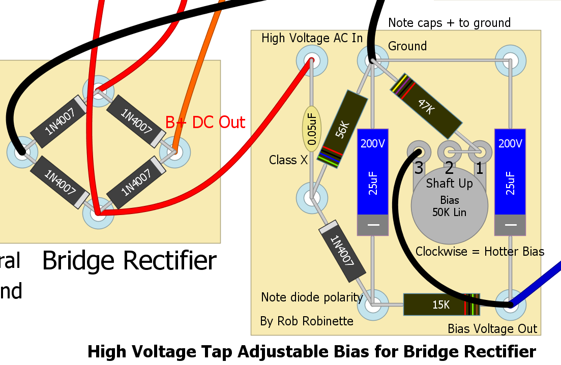
I also found this while poking around Rob’s site, a bias supply that seem to address this issue. I was going to copy this since I already have all the parts on hand but I still like the last bias supply design listed by Ten Over (and I appreciate it BTW), as I’d like to offer individually adjustable bias on this amp and probably future amp designs.
So is the capacitor at the input before the diode the only difference between the bias supply for CT vs. no-CT PT use, or is there more going on to it than that? And how crucial is the value of said capacitor?
Yoda wrote: ↑Sun Oct 22, 2023 4:37 am
… how crucial is the value of said capacitor?
The RC high pass filter component values before the bias rectifier largely determine the rectified V DC at the bias reservoir cap.
Such that if more voltage is required, the R or the C or both values could be increased.
pdf64 wrote: ↑Sun Oct 22, 2023 8:36 am
The RC high pass filter component values before the bias rectifier largely determine the rectified V DC at the bias reservoir cap.
Such that if more voltage is required, the R or the C or both values could be increased.
Increasing the value of C will increase the Vdc at the bias reservoir capacitor when all else is equal.
R is involved with the charge/discharge of C as well as with the biasing of the rectifier diode in conjunction with the reservoir capacitor. Because of this, there is an optimal value of R for any given C that will result in the highest DC voltage. For the Ampeg bias circuit from Rob above, the optimal R with a C of 0.05uF is in the 47k to 56k range. Values above or below this range will result in a lower DC voltage.
Yoda wrote: ↑Sun Oct 22, 2023 4:37 am
So is the capacitor at the input before the diode the only difference between the bias supply for CT vs. no-CT PT use, or is there more going on to it than that?
The Ampeg bias supply that you found on Rob's site is radically different than the typical bias supply found with a conventional, non-FWB HT supply (note that a CT is not a distinguishing feature of a conventional, non full wave bridge supply. Many FWB circuits utilize a CT, also.). The Ampeg circuit has a somewhat complex series of charge/discharge events and a series of diode forward/reverse bias events during each AC cycle. The typical old Fender bias supply is just a standard, half-wave power supply.