I'm posting this in a couple different spots to maximize the expertise of the forums I frequent, so here we go!
Howdy everyone,
I have a gutted Traynor YBA-1 that I've started building a Chieftain circuit into. I've been going by the Chieftain Reverb schematic posted on here, but I've made some tweaks.
The main modifications I've made are removing the reverb circuit, running a diode stack for rectification, deleting the standby switch, and using a resistor in place of a choke.
I opted to do these modifications for a few reasons. Regarding the reverb, I would never use it, and I'm trying to get away with using on-hand parts (meaning jacks, reverb transformer, pan, etc would require buying more stuff). The diode stack vs tube rectifier is due to my stock power transformer (Hammond 291JX equivalent) doesn't have a 5v tap on it. And lastly, the resistor-over-choke is due to the schematic calling for a 20H/160mA choke that I just cannot find for the life of me (likely a custom-built unit for Matchless) and I have a bunch of 1K 25W resistors kicking around from my minimum order when I did my Trainwreck Express build.
I passed on the standby switch because the original schematic calls for the standby switch to lift the ground for the HV centre tap, and my PT doesn't have a centre tap on the HV.
I've attached the original schematic as well as my modified one. The changes in components are in red, and the entire reverb circuit has been removed. I do have the turret board mounted with the components to add the reverb back in (along with needing the driver, jacks, and to drill out another hole for an additional preamp tube socket), but for now, I'm not going to use it.
Can anyone see issues with my updates?
Thanks in advance!
Input requested: Matchless Chieftain build (with original and modified schematics included)
Moderators: pompeiisneaks, Colossal
Input requested: Matchless Chieftain build (with original and modified schematics included)
You do not have the required permissions to view the files attached to this post.
Re: Input requested: Matchless Chieftain build (with original and modified schematics included)
Functionally it looks OK. Traynors always seemed to have high voltage B+ windings, so I'd check the AC voltage and do the math (Vp = 1.4 x Vac) to make sure the voltage at the first cap doesn't exceed its rating.

Re: Input requested: Matchless Chieftain build (with original and modified schematics included)
I'd get the biggest choke that will fit in the chassis. Even if it's only 5 or 10 Henries it will drastically improve your S/N ratio.
Tube junkie that aspires to become a tri-state bidirectional buss driver.
Re: Input requested: Matchless Chieftain build (with original and modified schematics included)
I've got the amp built, everything fires up and it makes nice guitar sounds. There are a couple gremlins I'm currently hunting down (motorboating when the treble pot is maxed, less overall gain than I was expecting).
One question I have is around pot wiring. I've always operated under the assumption that on a schematic, the top (looking left to right) most connection point is pin 1 and bottom is pin 3. Is this the case, or no?
I ask, because there's a Chieftain layout diagram floating around that doesn't match up to this logic.
Re: Input requested: Matchless Chieftain build (with original and modified schematics included)
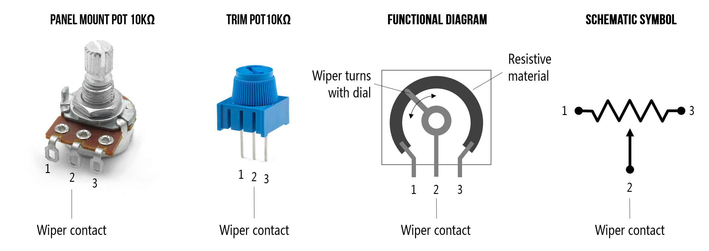
My understanding is that a regular volume control would wire lug 1 to common, 3 to signal in, 2 to signal out.
Schematics usually arrange things so that as the wiper is moved up, the thing it's adjusting increases.
My band:- http://www.youtube.com/user/RedwingBand

Re: Input requested: Matchless Chieftain build (with original and modified schematics included)
Not always. IMHO after 40 years of reading schematics it basically depends on who drew the schematic. Mind you the schematics I have experience with are everything from military equipment to CRT TV's to, most recently, tube amps. Sometimes pin numbers are indicated, sometimes there will be a CW or CCW with an arrow to indicate which rotation direction to increase or decrease something (signal level, resistance or???), often no additional clues are given.
A schematic is a logical representation of a circuit, not literal layout. I just look at a schematic logically and fortunately, on this forum, there are excellent layouts for the literal physical connections.
Glenn
Re: Input requested: Matchless Chieftain build (with original and modified schematics included)
That makes 100% sense. I’m grateful that whoever drew the schematics I worked off of included CW and CCW indicatorsGAStan wrote: ↑Thu Mar 21, 2024 3:59 pmNot always. IMHO after 40 years of reading schematics it basically depends on who drew the schematic. Mind you the schematics I have experience with are everything from military equipment to CRT TV's to, most recently, tube amps. Sometimes pin numbers are indicated, sometimes there will be a CW or CCW with an arrow to indicate which rotation direction to increase or decrease something (signal level, resistance or???), often no additional clues are given.
A schematic is a logical representation of a circuit, not literal layout. I just look at a schematic logically and fortunately, on this forum, there are excellent layouts for the literal physical connections.