
 768]http://i260.photobucket.com/albums/ii9/ ... G_0399.jpg[/img]
Its a 71 champ ..... if not please suggest the correct way to wire.
Moderators: pompeiisneaks, Colossal
768]http://i260.photobucket.com/albums/ii9/ ... G_0399.jpg[/img]
Thanks firestorm. I wasn't seeing the color right.Firestorm wrote:By the 70s, Fender was using universal transformers on these amps. They could be wired for 120VAC or 240VAC depending on how the taps were connected. See this link:
http://schematicheaven.com/fenderamps/champ_cbs.pdf
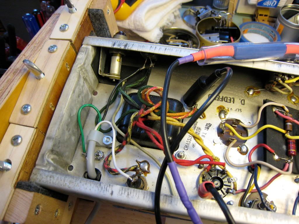
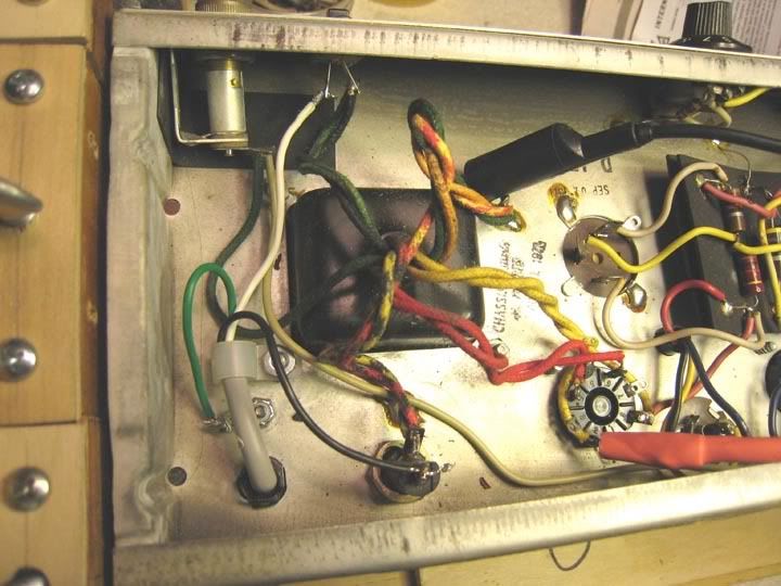
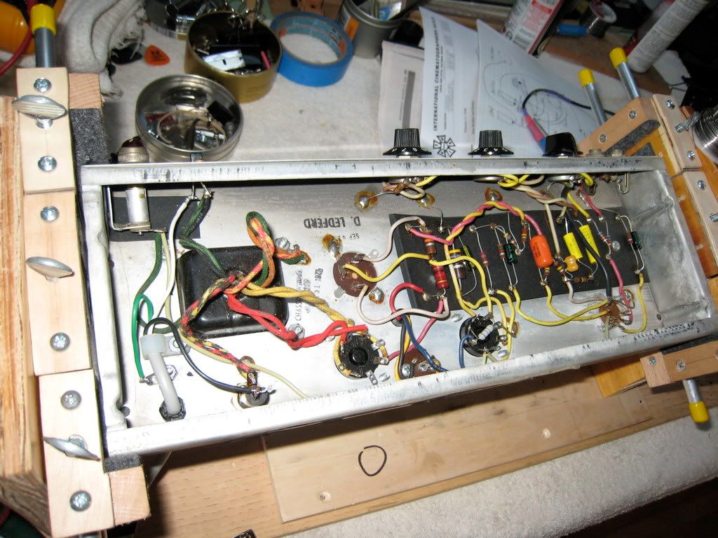
As far as I can tell from the pics posted, the heater wiring is CORRECT as is. That's actually a green wire on the piot lamp (the other one is grounded as are half the heater terminals on the tube sockets). The wire on the Switch is green-black -- part of the AC primary -- and it's right where it should be. The black and green-black wires together on one side and the black-red and black-yellow on the other side mean this PT is wired for 120VAC.
BTW, the extra lead (the dark yellow one I think) is a connection for an internal transformer shield. It goes to ground.
768]http://i260.photobucket.com/albums/ii9/ ... G_0414.jpg[/img]
