Yeah I had a layout all marked up with red lines to show the underboard wires, then I hit the wrong button and lost it.....
Maybe I'll try again tomorrow.
But, tribi, make sure you understand how that board is wired, like the dashed lines and such.
You are dealing with a lot of voltage here and the last thing I want to see is one of your relatives telling the forum that you were electrocuted.
So be damn careful ok?
My Very First Ever Build AA764 Vibro Champ. (Cab is here)
Moderators: pompeiisneaks, Colossal
Re: My Very First Ever Build AA764 Vibro Champ. (Cab is here)
Tom
Don't let that smoke out!
Don't let that smoke out!
Re: My Very First Ever Build AA764 Vibro Champ. (Cab is here)
Thx Mark.M Fowler wrote:I do not see the 330pf cap from pin 2 to pin 5 on the 6V6, it is shown on the schematic and layout. I had to down load your picture so I could blow it up to see better.
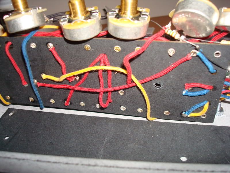
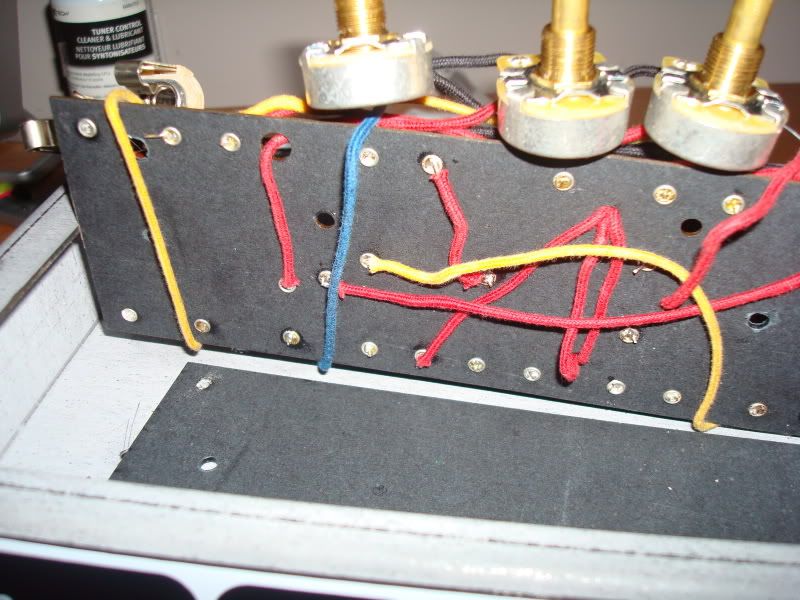
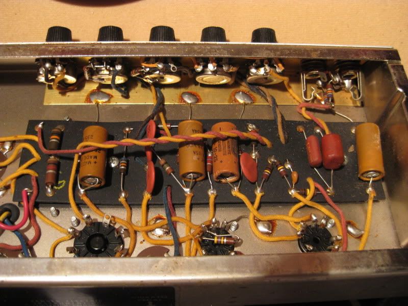
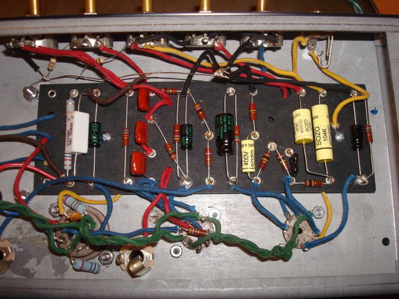
I am also concerned about under board wiring since we did not see any pictures of that. There is a lot going on in that layout most of which are just wires passing under the board but the other ones also indicated by dashes on the layout are connections.
Mark
I'm using the layout from this site.
http://www.thevintagesound.com/ffg/sche ... layout.gif
This schematic doesn't show that 330 pf cap on the 6V6.
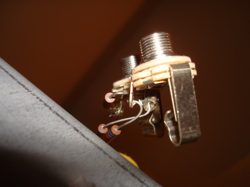
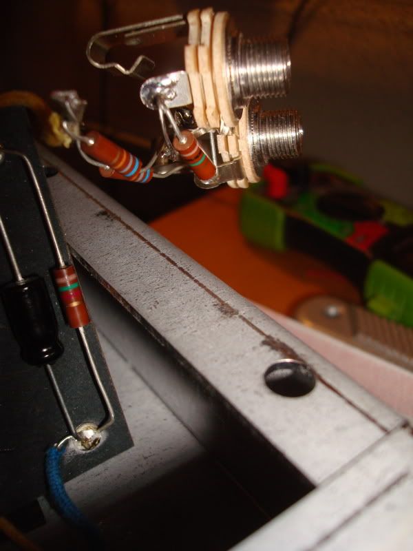
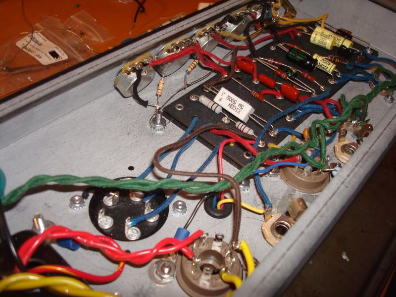
Here are a couple of pics of under the board.
[IMG:800:600]http://i114.photobucket.com/albums/n271 ... C01985.jpg[/img]
[IMG:800:600]http://i114.photobucket.com/albums/n271 ... C01986.jpg[/img]
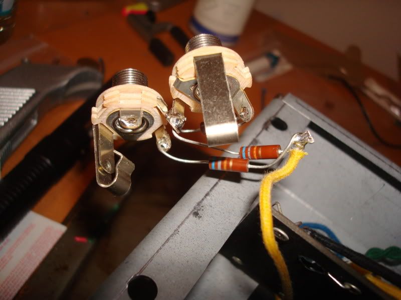
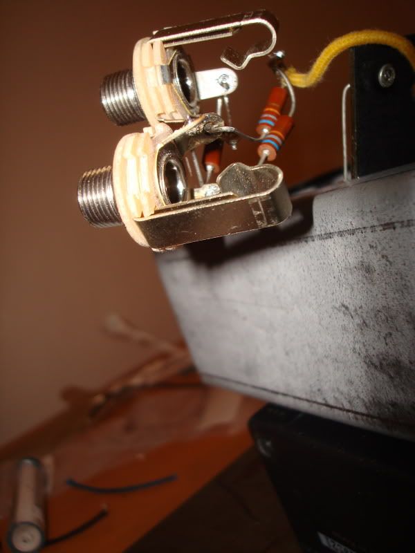
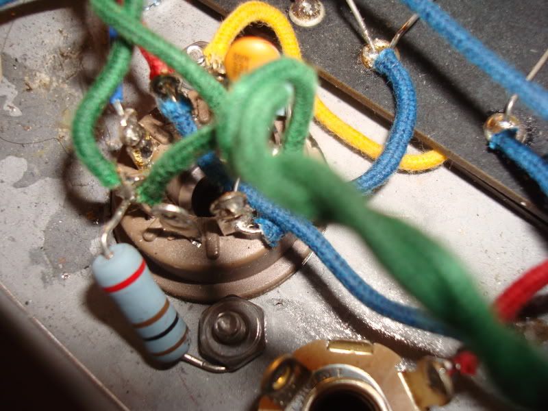
360 view of the jack.
[IMG:800:600]http://i114.photobucket.com/albums/n271 ... C01987.jpg[/img]
[IMG:600:800]http://i114.photobucket.com/albums/n271 ... C01988.jpg[/img]
[IMG:800:600]http://i114.photobucket.com/albums/n271 ... C01989.jpg[/img]
[IMG:600:800]http://i114.photobucket.com/albums/n271 ... C01990.jpg[/img]
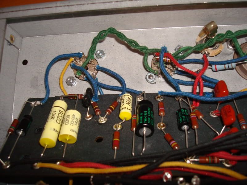
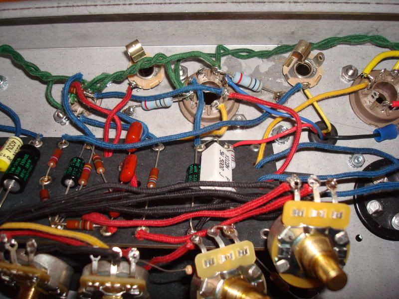
The board.
[IMG:800:600]http://i114.photobucket.com/albums/n271 ... C01991.jpg[/img]
[IMG:800:600]http://i114.photobucket.com/albums/n271 ... C01992.jpg[/img]
Last edited by tribi9 on Wed May 13, 2009 5:42 am, edited 1 time in total.
Re: My Very First Ever Build AA764 Vibro Champ. (Cab is here)
No problem. I'll be extra careful.Structo wrote:Yeah I had a layout all marked up with red lines to show the underboard wires, then I hit the wrong button and lost it.....
Maybe I'll try again tomorrow.
But, tribi, make sure you understand how that board is wired, like the dashed lines and such.
You are dealing with a lot of voltage here and the last thing I want to see is one of your relatives telling the forum that you were electrocuted.
So be damn careful ok?
Thank you Structo.
Re: My Very First Ever Build AA764 Vibro Champ. (Cab is here)
Yeah it's really hard to tell from your pictures whats wrong.
I do see a few eyelets I would touch up.
The one eyelet that the 220K resistor by point X doesn't look like it is soldered.
You do know that everything that has that little triangle is a ground right?
Except for the heater wiring where we decided that the grounded heater was not a good thing.
Just the 100R artificial center tap goes to ground there.
As was mentioned, I know you want to get this thing going but it's best sometimes to just walk away for a day or so, then come back with a fresh mind and check it from the output to the input, verifying each connection with the layout.
You got some hum so you are getting closer.
Another thing you could try is to just wire a jack to the grid of V1 (pin 2) without the jacks you already have connected and plug your guitar in and see if you get a guitar through the amp.
If that works then you know the problem is with the jacks and the way you have them wired.
Do you know how to measure the voltages at the proper places?
Ground your black probe to the chassis and with one hand
touch the red probe on the plate resistor of each tube and write those numbers down with the pin # next to it.
See the three wires coming off of the cap can?
Measure those voltages where they connect to the resistors at the board.
Your numbers should be somewhat close to the numbers on the layout.
Your maybe higher due to the higher wall voltages of today.
You need to be able to read a schematic too.
This file has the schematic on page 1 and the layout on page 2.
The schematic has voltages on it near the pins of the tubes.
Remember the sockets are numbered clockwise from the bottom and start counting after the gap.
http://www.schematicheaven.com/fenderam ... _schem.pdf
So measure some voltages and tell us where you are at.
I like to use a red sharpie and as I check each solder joint I color it red, so I can keep track of where I'm at.
Plus it looks cool.
Tom
Don't let that smoke out!
Don't let that smoke out!

Re: My Very First Ever Build AA764 Vibro Champ. (Cab is here)
What happened to the first layout you posted that showed the 330pf on the 6V6 it doesn't matter but my reference was based on that posted layout/schematic earlier not this current layout.
Mark
Mark
Re: My Very First Ever Build AA764 Vibro Champ. (Cab is here)
Mark, the first layout I posted I believe has a voltage number showing on the tube. I believe the layout for the 'Bronco" amp has that cap on the 6V6.M Fowler wrote:What happened to the first layout you posted that showed the 330pf on the 6V6 it doesn't matter but my reference was based on that posted layout/schematic earlier not this current layout.
Mark
Sorry for the misunderstanding.
Structo.
I will take a 1 day break and start with a fresh layout and highlight each connection and check mark the solder joints.
I can't measure voltages yet as the hum is actually quite loud and I don't want to damage the cab I'm using. I'm just not sure how long I can keep it on before something gets messed up.
I think I also need to come up with a new ground plan for all the connections on the board (On the pot side) As it looks a little messy. Maybe drill a couple of holes and ground the connections to 2 points?
I will wire the the input jack to pin 2 on the 12AX7 and let you guys know.
Again guys, thanks for all the support.
Ronald

Re: My Very First Ever Build AA764 Vibro Champ. (Cab is here)
Gather all your preamp grounds together and put them on a floating ground...one that is insulated from the chassis.
Put all your high potential grounds (filter caps, output transformer, power tube cathode, PT center tap, anything that isn't connected somehow to the 12AX7's, and put those all on the ONE bolt near the power transformer. This one IS grounded to the chassis.
Then, connect that floating ground to the main ground with one single wire.
While not foolproof, in this sort of amp, it should do a reasonable job of minimizing ground induced hum.
You are doing a good job of keeping at it. I agree that a short break might be beneficial.
When you finally get it to pass an instrument signal to the speaker (this WILL happen!), there will be a bit of wiring clean up. I don't mean to be unkind. This is your first build? You're doing OK. But your wiring layout (lead dress) isn't up to snuff and will probably give you some issues to deal with.
Once you get to the point of looking at lead dress, you are on the home stretch.
Re: My Very First Ever Build AA764 Vibro Champ. (Cab is here)
Yes, I didn't want to get too critical because you are having such issues.
But, you should look at some pictures of similar Fender amps to see how they are lead dressed.
For instance, the heater wires on a Fender amp are traditionally ran up in the air.
In other words, they are ran above the sockets, then come down straight to the pins.
This way you can keep the other wires, particularly the grid wires away from them. The grid wires (Pins 2 & 7) should be kept as short as possible or you can get noise or oscillations.
Here is a great piece written by Gil Ayan about lead dress.
You may want to print it out, it's a great resource.
http://www.ayanmusic.com/leaddress.htm
Tom
Don't let that smoke out!
Don't let that smoke out!
Re: My Very First Ever Build AA764 Vibro Champ. (Cab is here)
Please feel free to comment/criticize whatever it is you feel necessary. I just take it as a valuable lesson anywayPhil_S wrote:Gather all your preamp grounds together and put them on a floating ground...one that is insulated from the chassis.
Put all your high potential grounds (filter caps, output transformer, power tube cathode, PT center tap, anything that isn't connected somehow to the 12AX7's, and put those all on the ONE bolt near the power transformer. This one IS grounded to the chassis.
Then, connect that floating ground to the main ground with one single wire.
While not foolproof, in this sort of amp, it should do a reasonable job of minimizing ground induced hum.
You are doing a good job of keeping at it. I agree that a short break might be beneficial.
When you finally get it to pass an instrument signal to the speaker (this WILL happen!), there will be a bit of wiring clean up. I don't mean to be unkind. This is your first build? You're doing OK. But your wiring layout (lead dress) isn't up to snuff and will probably give you some issues to deal with.
Once you get to the point of looking at lead dress, you are on the home stretch.
I found this pic on a different forum and Iḿ going to see if I can find one of those brass plates. I asked Mojotone and they said they don have them.
[IMG:800:600]http://i114.photobucket.com/albums/n271 ... G_2345.jpg[/img]
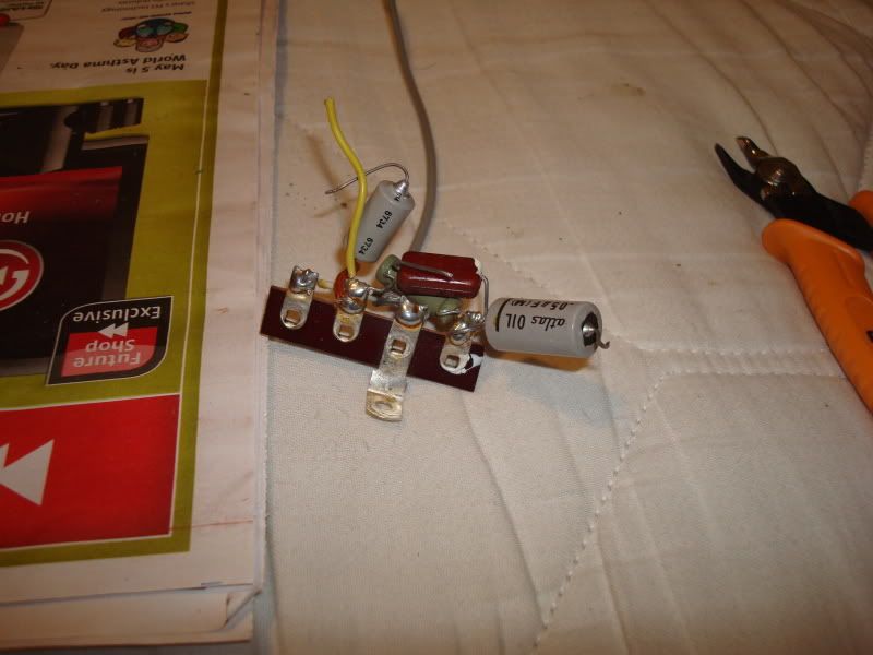
I was thinking that maybe then for the grounds on the front, to use a copper bus wire on the back of the pots. That way I can ground the spots from the board that also need to be grounded with a short wire. I found this from an old amp so I might put it to use. I don know if I can cut it without breaking it tho
[IMG:800:600]http://i114.photobucket.com/albums/n271 ... c02007.jpg[/img]
The leads I think I might redo the heaters with 22 awg along with the inputs.
Iḿ going over the connections tomorrow night with a highlighter. One by one against the layout.
Re: My Very First Ever Build AA764 Vibro Champ. (Cab is here)
Thank you,Structo wrote:Yes, I didn't want to get too critical because you are having such issues.
But, you should look at some pictures of similar Fender amps to see how they are lead dressed.
For instance, the heater wires on a Fender amp are traditionally ran up in the air.
In other words, they are ran above the sockets, then come down straight to the pins.
This way you can keep the other wires, particularly the grid wires away from them. The grid wires (Pins 2 & 7) should be kept as short as possible or you can get noise or oscillations.
Here is a great piece written by Gil Ayan about lead dress.
You may want to print it out, it's a great resource.
http://www.ayanmusic.com/leaddress.htm
I will go through the link before my next attempt tomorrow night.
Re: My Very First Ever Build AA764 Vibro Champ. (Cab is here)
Yeah, personally I wouldn't use the brass plate.
It acts like a heat sink and unless you have an 100 watt iron it will be difficult to solder to.
I would use a ground buss.
But, I wouldn't solder it to the back of the pots.
You can either run it across the board on the side towards the pots or have it hang off the lugs on the pots that go to ground.
While that is a great photo of a vintage amp, it uses the old style of heater wiring where they grounded half of the circuit.
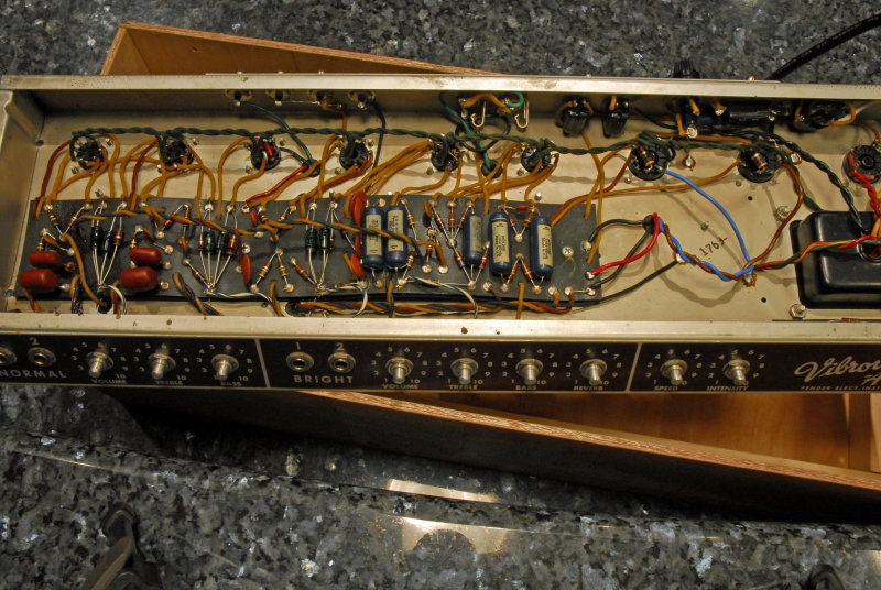
This isn't the greatest gut shot but you can see the heater wires and how they are run from above.
[img:800:536]http://www.pbase.com/cwilliamrose/image ... /large.jpg[/img]
It acts like a heat sink and unless you have an 100 watt iron it will be difficult to solder to.
I would use a ground buss.
But, I wouldn't solder it to the back of the pots.
You can either run it across the board on the side towards the pots or have it hang off the lugs on the pots that go to ground.
While that is a great photo of a vintage amp, it uses the old style of heater wiring where they grounded half of the circuit.
This isn't the greatest gut shot but you can see the heater wires and how they are run from above.
[img:800:536]http://www.pbase.com/cwilliamrose/image ... /large.jpg[/img]
Tom
Don't let that smoke out!
Don't let that smoke out!
Re: My Very First Ever Build AA764 Vibro Champ. (Cab is here)
On grounding: You have an unused eyelet on the "pot" side, at the end, near the power transformer. Run a ground buss from the ground side of the first eyelet on that side (cathode r/c ground) to the unused eyelet or just take it directly to the chassis near the input jacks, see below.
Tie all your preamp grounds to the buss. A buss is simply an uninsulated solid wire. Don't go larger than 20ga or you will have some difficulty soldering to it and pre-tin any spots you want to attach something.
The buss is a floating ground like I described before. I've reconsidered the one wire to the main bolt; don't do that. You've got Switchcraft jacks (not inulated), so make your chassis ground for the buss near the jacks. I usually work with Cliff-type jacks which are insulated and lost sight of this.
On filament wiring: 22ga is not fat enough. 18ga is recommended. I often use 20ga solid for 9-pin sockets simply because it is difficult to double thread the tube pins with 18ga. Yours isn't awful. Wait to see if it's a problem before you fiddle with it.
Your first concern is to get the amp to pass a signal to the speaker. Everything else, you do later. Although some of what you have done may not be up to what we like to see, some amps, for reasons that are not totally understood, are very forgiving. I suggest you don't look to fix a problem that may not exist.
Re: My Very First Ever Build AA764 Vibro Champ. (Cab is here)
Phil_S wrote:
Your first concern is to get the amp to pass a signal to the speaker. Everything else, you do later. Although some of what you have done may not be up to what we like to see, some amps, for reasons that are not totally understood, are very forgiving. I suggest you don't look to fix a problem that may not exist.
Ok, I will work on getting it to function then I will tackle the rest.
Thank you.
Re: My Very First Ever Build AA764 Vibro Champ. (Cab is here)
Thanks for the pic.Structo wrote:Yeah, personally I wouldn't use the brass plate.
It acts like a heat sink and unless you have an 100 watt iron it will be difficult to solder to.
I would use a ground buss.
But, I wouldn't solder it to the back of the pots.
You can either run it across the board on the side towards the pots or have it hang off the lugs on the pots that go to ground.
While that is a great photo of a vintage amp, it uses the old style of heater wiring where they grounded half of the circuit.
This isn't the greatest gut shot but you can see the heater wires and how they are run from above.
[img:800:536]http://www.pbase.com/cwilliamrose/image ... /large.jpg[/img]
Re: My Very First Ever Build AA764 Vibro Champ. (Cab is here)
I worked a bit on the amp. I raised the heater wires and double checked all the connections. I sat down with the layout and a highlighter with the board unscrewed and verified every single under the board connection. Once they all checked out, I decided to make a temporary ground for everything on the pot side and to just focus on getting sound so I put it back together. Used just some of the wire from the cloth wire for the temporary ground bus. I highlighter checked again all the connections on a new printout. Everything checked out, so I decided to plug in. This time the amp was quiet, no sound, no hum.
So because there was no hum I decided to take voltages. I took whatever was on the layout marked with a Voltage. They all checked out. Voltages were actually a bit lower by about 20 Volts actually but I had plugged in the amp into a power bar. I was actually a bit worried because of it not making any noise. I verified 6.3 Volts on the heaters as well.
I looked over at the schematic and noticed one ground I hadn't checked out. It was the big cathode resistor ground. So I grounded it. I plugged in again and this time I got hum, but the hum starts getting gradually louder. (I don't let it get too loud, I turn off the amp)
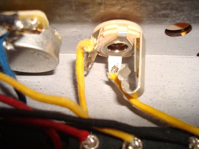
I'm not really sure where the mistake can be. The only thing that is not the same as the schematic is the input jack. I just got the tip wired straight to pin 2 on V1. I grounded it as well but I guess It doesn't need a ground because the sleeve is grounded to chassis anyway. Could that be the culprit. I had it grounded according to the one picture Phil S. posted, but just wanted to try wiring it straight to pin 2.
One thing tho is I never wrote the voltages down the first time and now the amp gets too loud for me to take them again even if I have the volume knob all the way down.
I'm also using speaker cable on the output jack.
[IMG:800:600]http://i114.photobucket.com/albums/n271 ... c02028.jpg[/img]
[IMG:800:600]http://i114.photobucket.com/albums/n271 ... c02024.jpg[/img]
[IMG:800:600]http://i114.photobucket.com/albums/n271 ... c02026.jpg[/img]
[IMG:800:600]http://i114.photobucket.com/albums/n271 ... c02025.jpg[/img]
So because there was no hum I decided to take voltages. I took whatever was on the layout marked with a Voltage. They all checked out. Voltages were actually a bit lower by about 20 Volts actually but I had plugged in the amp into a power bar. I was actually a bit worried because of it not making any noise. I verified 6.3 Volts on the heaters as well.
I looked over at the schematic and noticed one ground I hadn't checked out. It was the big cathode resistor ground. So I grounded it. I plugged in again and this time I got hum, but the hum starts getting gradually louder. (I don't let it get too loud, I turn off the amp)
I'm not really sure where the mistake can be. The only thing that is not the same as the schematic is the input jack. I just got the tip wired straight to pin 2 on V1. I grounded it as well but I guess It doesn't need a ground because the sleeve is grounded to chassis anyway. Could that be the culprit. I had it grounded according to the one picture Phil S. posted, but just wanted to try wiring it straight to pin 2.
One thing tho is I never wrote the voltages down the first time and now the amp gets too loud for me to take them again even if I have the volume knob all the way down.
I'm also using speaker cable on the output jack.
[IMG:800:600]http://i114.photobucket.com/albums/n271 ... c02028.jpg[/img]
[IMG:800:600]http://i114.photobucket.com/albums/n271 ... c02024.jpg[/img]
[IMG:800:600]http://i114.photobucket.com/albums/n271 ... c02026.jpg[/img]
[IMG:800:600]http://i114.photobucket.com/albums/n271 ... c02025.jpg[/img]