Could be, what is the total heater amperage being drawn?
4 x 12A*7 @ .300A = 1.2A
2 x 6V6 @ .45A = .9A
Rectifier = .5A, maybe.
Is this pulling over the rated amperage on the heaters?
Pull 2 preamp tubes and see if it runs better.
New Princeton Reverb build--Low B+ post -GZ34
Moderators: pompeiisneaks, Colossal
-
sonofmickel
- Posts: 118
- Joined: Sun Jan 13, 2008 4:56 pm
Re: New Princeton Reverb build--Low B+ post -GZ34
The problem is pretty obvious just by looking at the measured voltages. Screen voltage is ≈ 320V and bias voltage on control grid ≈ -12V. Under these conditions each 6V6 is drawing maybe 80mA, no wonder the B+ is sagging so low with power transformer with secondary rated "650/550Vct @ 100 mA". Now you should find out why the bias voltage is only -12V, it should be somewhere around -30V. My guess would be there is something wrong in the bias circuit. Another possibility is that the amp is oscillating which may mess up the bias voltage.
-
Stevem
- Posts: 4602
- Joined: Fri Jan 24, 2014 3:01 pm
- Location: 1/3rd the way out one of the arms of the Milkyway.
1 others liked this
Re: New Princeton Reverb build--Low B+ post -GZ34
I see the amp has a bias adjust pot behind the speed control, so the thing to do is to yank out the outout tubes and hook your meter across pin 5 and ground and then adjust that bias pot from end to end and report back here with the negative range of voltage that you have.
Do not run the amp any more with the output tubes in it until we trace down what's going on, or if you can get the -V on pin 5 up to atleast-30 volts then it will be ok to put the tubes back in.
Do not run the amp any more with the output tubes in it until we trace down what's going on, or if you can get the -V on pin 5 up to atleast-30 volts then it will be ok to put the tubes back in.
When I die, I want to go like my Grandfather did, peacefully in his sleep.
Not screaming like the passengers in his car!
Cutting out a man's tongue does not mean he’s a liar, but it does show that you fear the truth he might speak about you!
Not screaming like the passengers in his car!

Cutting out a man's tongue does not mean he’s a liar, but it does show that you fear the truth he might speak about you!

Re: New Princeton Reverb build--Low B+ post -GZ34
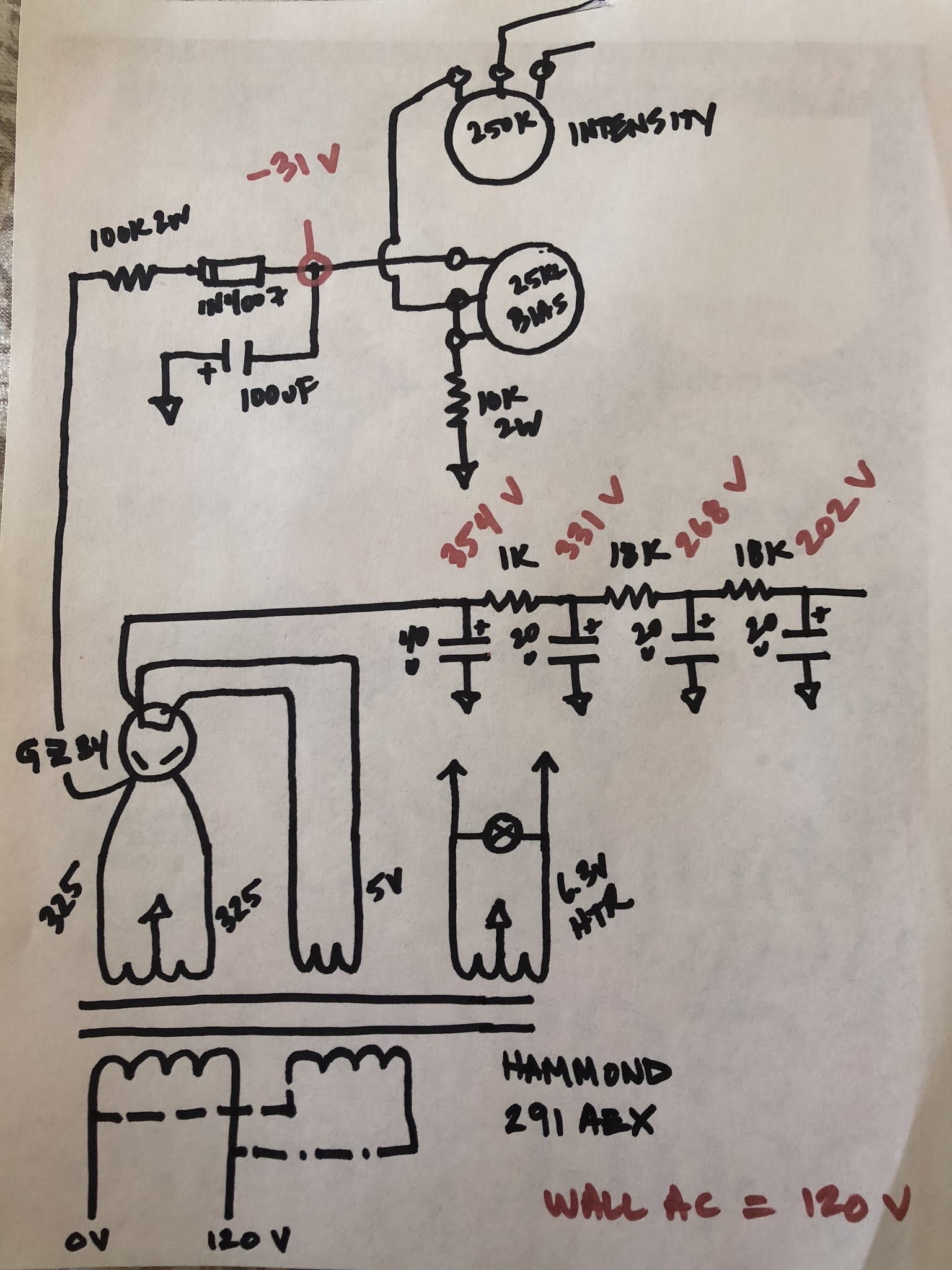
Thanks all for the tips. We have a “scheduled power outage “ here at the house so here’s a schematic courtesy of Sharpie 1.0:
The bias pot shaft is DOWN. Perhaps this is wrong?
The bias pot shaft is DOWN. Perhaps this is wrong?
Just plug it in, man.
-
pompeiisneaks

- Site Admin
- Posts: 4222
- Joined: Sat Jan 14, 2017 4:36 pm
- Location: Washington State, USA
- Contact:
Re: New Princeton Reverb build--Low B+ post -GZ34
Not sure what you mean by 'down' you can rotate it fully either direction and write down what the voltage values are at each end (still with power tubes out) and then set it to maximum negative voltage. i.e. you read -30 now, say the other end is -50. -50 is maximum and would be the coldest you can bias the power tubes. Then you can adjust the bias once the power tubes are back in to the right current rating for them, so they're not redplating. (of course I don't know WHAT yours will read, but let us know what you get at either end of the pot's turn.
~Phil
~Phil
tUber Nerd!

Re: New Princeton Reverb build--Low B+ post -GZ34
In general, the orientation of the pt shaft as shown in your pictures allows you to drill a hole in the deck so you can have access without opening the chassis. This arrangement is usually accompanied by the installation of test points, so that you can plug your meter probes into the test points. If you have no test points installed, either install them or flip the pot over so you can do the whole job with the chassis open.
Re: New Princeton Reverb build--Low B+ post -GZ34
Phil_S wrote: ↑Fri Nov 20, 2020 8:15 pmIn general, the orientation of the pot shaft as shown in your pictures allows you to drill a hole in the deck so you can have access without opening the chassis. This arrangement is usually accompanied by the installation of test points, so that you can plug your meter probes into the test points. If you have no test points installed, either install them or flip the pot over so you can do the whole job with the chassis open.
Re: New Princeton Reverb build--Low B+ post -GZ34
Thanks, Phil. I say “down” only to orient the pot on my drawing. The pot is installed with the shaft sticking outside the chassis. I’ve used a TAD bias master in the past and wanted the option of not pulling the chassis to adjust the bias. I can see how test points would be better.pompeiisneaks wrote: ↑Fri Nov 20, 2020 8:03 pm Not sure what you mean by 'down' you can rotate it fully either direction and write down what the voltage values are at each end (still with power tubes out) and then set it to maximum negative voltage. i.e. you read -30 now, say the other end is -50. -50 is maximum and would be the coldest you can bias the power tubes. Then you can adjust the bias once the power tubes are back in to the right current rating for them, so they're not redplating. (of course I don't know WHAT yours will read, but let us know what you get at either end of the pot's turn.
~Phil
Just plug it in, man.
-
martin manning

- Posts: 13327
- Joined: Sun Jul 06, 2008 12:43 am
- Location: 39°06' N 84°30' W
Re: New Princeton Reverb build--Low B+ post -GZ34
Here's a better bias circuit in Sharpie 2.0 (chisel tip). First resistor is 68k, then 10k after the diode, 10k bias pot (standard Fender with screwdriver slot), and 15k to ground. The caps are 10u and 22u. Your 100u will be very slow to charge given the 100k in front of it. The extra cap on the output will keep the ripple low. The bias pot is wired in a fail-safe way, too.
You do not have the required permissions to view the files attached to this post.
Re: New Princeton Reverb build--Low B+ post -GZ34
Chisel tip. Noted.
I wonder if my bias pot is wired incorrectly? Thank you for your input. I may test this version out very soon.
I wonder if my bias pot is wired incorrectly? Thank you for your input. I may test this version out very soon.
Just plug it in, man.
Re: New Princeton Reverb build--Low B+ post -GZ34
Why not do as requested several post back? Only take 1 minute...
***PULL THE 6V6s FOR THIS TEST***
Rotate the bias pot shaft fully clockwise. Measure and record the voltage on pin 5 of a 6V6 socket. Now, Rotate the bias pot shaft fully counterclockwise. Measure and record the voltage on pin 5 of a 6V6 socket. Tell us what two numbers you recorded.
This may sound stupid but it tells us what range of bias voltage your circuit currently has. Maybe the range is already correct for 6V6s. Maybe not. If not, we will now be able to suggest a simple change to your circuit to provide an adequate bias range for your 6V6s.
-
martin manning
- Posts: 13327
- Joined: Sun Jul 06, 2008 12:43 am
- Location: 39°06' N 84°30' W
Re: New Princeton Reverb build--Low B+ post -GZ34
Your bias circuit should deliver about -30V at mid point, so no worries, but I would consider the one above to get the bias voltage established more quickly. Maybe something in your vibrato circuit is dragging the bias voltage up, like a leaky blocking cap? Measure your bias voltage as is, and if it is too high, try disconnecting the 250k intensity pot.
Re: New Princeton Reverb build--Low B+ post -GZ34
Ok, I pulled the power tubes and measured the following:
-14.5 VDC
-12.5 VDC
These are the voltage readings on power tube socket pin 5s on both ends of the bias pot. The voltage as marked on the drawing is -31 V after the diode (via adjustment). "Perchance something is amiss."
-14.5 VDC
-12.5 VDC
These are the voltage readings on power tube socket pin 5s on both ends of the bias pot. The voltage as marked on the drawing is -31 V after the diode (via adjustment). "Perchance something is amiss."
Just plug it in, man.
Re: New Princeton Reverb build--Low B+ post -GZ34
I suspect your amp is not wired IAW your drawing.
Re: New Princeton Reverb build--Low B+ post -GZ34
I cannot disagree. Not sure what to do next.
I drew the "power string" as requested, I'm using a 40/20/20/20 uF can cap. The PT grids connect to B+2. Other than that, I believe the drawing reflects the circuit, swear on my wife's poodle.
I'm going to look it over again, but I'm stumped.
The Hammond 291AEX uses a 6.3 V CT, so I grounded that in lieu of an artificial heater CT off of the lamp.
All of the power string connections appear to be in line on the board. No idea about the tremolo blocking caps. The only change I made there was I used a 0.01/0.02/0.02 arrangement as opposed to the normal 0.01/0.01/0.02.
Thanks for looking at this.
Just plug it in, man.