... from the trem circuit. That way you should have the bias supply isolated. It's the 0.1u cap I'm wondering about.martin manning wrote: ↑Fri Nov 20, 2020 10:49 pmMeasure your bias voltage as is, and if it is too high, try disconnecting the 250k intensity pot.
New Princeton Reverb build--Low B+ post -GZ34
Moderators: pompeiisneaks, Colossal
-
martin manning

- Posts: 13371
- Joined: Sun Jul 06, 2008 12:43 am
- Location: 39°06' N 84°30' W
1 others liked this
Re: New Princeton Reverb build--Low B+ post -GZ34

Re: New Princeton Reverb build--Low B+ post -GZ34
Operation: disconnect intensity pot.
Mission outcome: 6V6 red-plating.
The bias voltage ranges between -14.5 and -46 VDC on the bias diode, but that is the same even with the intensity pot connected. I could always detect a wide range there, just not on the 6V6 pin 5s. With the intensity pot disconnected, I get less than 1 volt on the pin 5s and orange plates on the 6V6s. FUN!
Just plug it in, man.
-
martin manning
- Posts: 13371
- Joined: Sun Jul 06, 2008 12:43 am
- Location: 39°06' N 84°30' W
Re: New Princeton Reverb build--Low B+ post -GZ34
I think you disconnected the wrong end.
Re: New Princeton Reverb build--Low B+ post -GZ34
Indeed. I owe you some facepalm ointment, don't I? Sorry.
Well, I reconnected the power tubes to the bias circuit (Yay!), and disconnected the intensity pot on the *correct side*. Same results. I decided to probe the PT 5V winding and I get the (relatively low) rectified DC on the end attached to the filter cap and the other end I get wildy changing voltages. Anything to be concerned with there?
Just plug it in, man.
-
sluckey
- Posts: 3113
- Joined: Sun Jul 22, 2007 7:48 pm
- Location: Mobile, AL
- Contact:
2 others liked this
Re: New Princeton Reverb build--Low B+ post -GZ34
Disconnect the .1µF cap from the INT pot but leave the INT pot in the circuit. The bias voltage has to go through the INT pot to get to the 6V6 grids. Look at the schematic. And pull those 6V6s and hide them. DON'T PUT THEM BACK IN UNTIL YOU HAVE PROPER NEGATIVE BIAS VOLTAGE ON SOCKET PINS 5.
You must fix this issue before proceeding with any more testing.
You must fix this issue before proceeding with any more testing.
-
pompeiisneaks

- Site Admin
- Posts: 4222
- Joined: Sat Jan 14, 2017 4:36 pm
- Location: Washington State, USA
- Contact:
1 others liked this
Re: New Princeton Reverb build--Low B+ post -GZ34
In case you missed it
DO
NOT
PUT
IN
POWER
TUBES
UNTIL
YOU
FIX
NEGATIVE
BIAS

not sure if that is clear yet?
~Phil
DO
NOT
PUT
IN
POWER
TUBES
UNTIL
YOU
FIX
NEGATIVE
BIAS
not sure if that is clear yet?
~Phil
tUber Nerd!
Re: New Princeton Reverb build--Low B+ post -GZ34
Sooooo, whaddayameanexactly?
Copy that, and thank you for the recommendation. For all intents and purposes, consider them at the bottom of the f@cking ocean. They’re OUT. BOXED. TAPED. LOCKEDINALCAPONESVAULTWITHCOBRASANDSH!T.

I will return and report. And again, thanks guys. Many thanks.
Copy that, and thank you for the recommendation. For all intents and purposes, consider them at the bottom of the f@cking ocean. They’re OUT. BOXED. TAPED. LOCKEDINALCAPONESVAULTWITHCOBRASANDSH!T.
I will return and report. And again, thanks guys. Many thanks.
Just plug it in, man.
Re: New Princeton Reverb build--Low B+ post -GZ34
Very good. Next episode:
I disconnected one leg of that 0.1 uF tremolo blocking cap and soldered a wire in its place.
The value of the cap tests at 101 nF, right on target.
I now have Costco-sized B+ voltage coming off of the rectifier socket at over 450 VDC.
Power tube sockets pin 5s... still the same. When I wind the adjustment pot, the voltage shoots down (more negative at around -25 VDC) and then rises back up to -10 to -12 VDC, turn to turn.
Just plug it in, man.
Re: New Princeton Reverb build--Low B+ post -GZ34
Facepalm more-than-2.0. 
When you said leave the intensity pot in the circuit, I misunderstood what you meant. You meant the “bias circuit”, not the tremolo, yes? Running on that assumption, I cut the replacement wire and left the 0.1uF blocking cap out of the circuit.
Amp on, same high rectifier voltage, no change to power tube pin 5 voltages.
Just plug it in, man.
-
sluckey
- Posts: 3113
- Joined: Sun Jul 22, 2007 7:48 pm
- Location: Mobile, AL
- Contact:
1 others liked this
Re: New Princeton Reverb build--Low B+ post -GZ34
I don't know why this simple circuit is being so difficult. So, let's divide and conquer.
Try this... There is a yellow wire between the INT pot and the BIAS pot. Disconnect the end of that yellow wire at the bias pot. Connect your volt meter to the wiper of the bias pot. Turn the shaft all the way to the end and note the voltage reading. Now turn the shaft of the bias pot all the way to the other end and note the voltage reading. What are the two readings?
Try this... There is a yellow wire between the INT pot and the BIAS pot. Disconnect the end of that yellow wire at the bias pot. Connect your volt meter to the wiper of the bias pot. Turn the shaft all the way to the end and note the voltage reading. Now turn the shaft of the bias pot all the way to the other end and note the voltage reading. What are the two readings?
Re: New Princeton Reverb build--Low B+ post -GZ34
Always great to have a wingman, comedy of errors be damned! Thanks.
After disconnecting that wire as you mentioned, I get the same limited voltage range on the bias pot wiper as I do on the “5-pins”. The turret at the end of the orange wire reads a normal range between -20 and about -42 VDC.
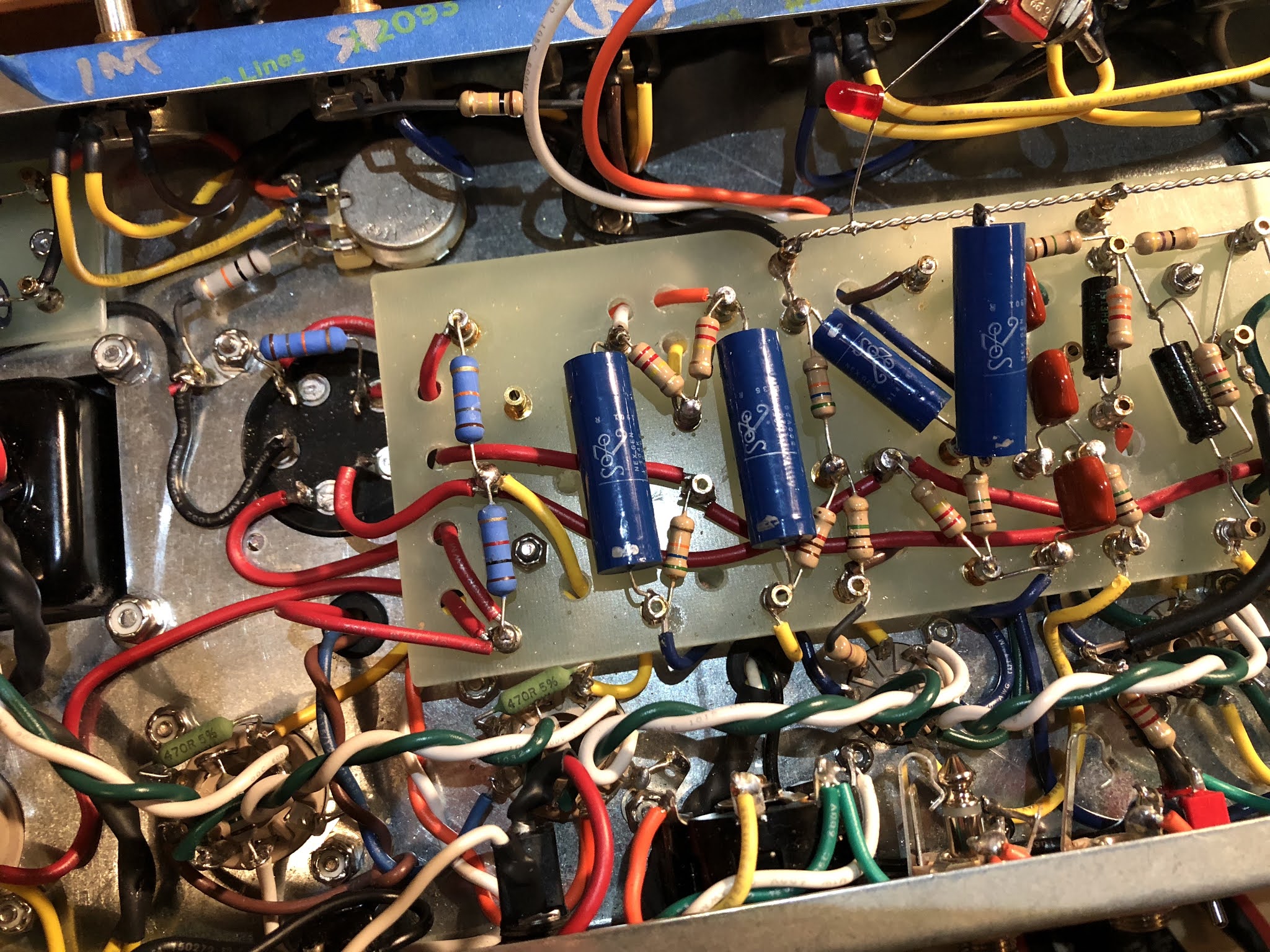
The 10K resistor-to-ground on the bias pot is tied to the wiper also, like my Sharpie schematic. Hard to see in the photo.
After disconnecting that wire as you mentioned, I get the same limited voltage range on the bias pot wiper as I do on the “5-pins”. The turret at the end of the orange wire reads a normal range between -20 and about -42 VDC.
The 10K resistor-to-ground on the bias pot is tied to the wiper also, like my Sharpie schematic. Hard to see in the photo.
Just plug it in, man.
Re: New Princeton Reverb build--Low B+ post -GZ34
If you disconnected the wire as I said, there is no way for bias voltage to get to the board. What orange wire are you talking about? Why can't you just follow instructions and post the voltage readings I asked for?
Re: New Princeton Reverb build--Low B+ post -GZ34
With the yellow wire between the intensity pot lug 3 and bias pot wiper disconnected, the bias pot wiper reads:
-12.5 VDC
-14.5 VDC
at both ends of the pot’s adjustment range.
The orange wire connects the bias pot lug 1 to the bias circuit diode to the left. The diode turret reads -20 or so to -42 VDC end to end with bias pot adjustment.
[Edit: The buy-low opportunity on Minoxidil stock was about 10 posts ago. ]
Just plug it in, man.
Re: New Princeton Reverb build--Low B+ post -GZ34
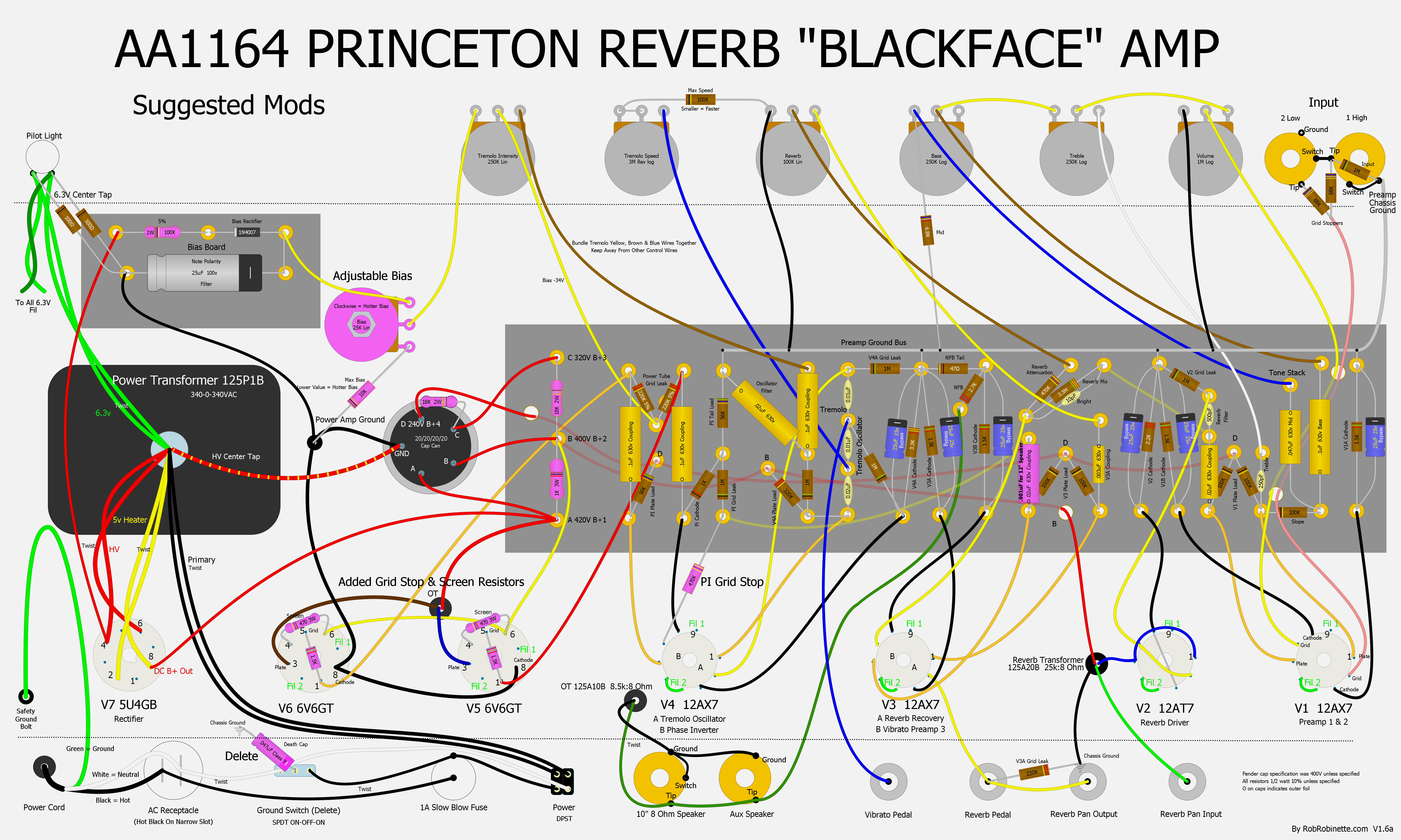
Here’s the bias adjustment wiring I followed, although my pot is shaft-down:
Just plug it in, man.