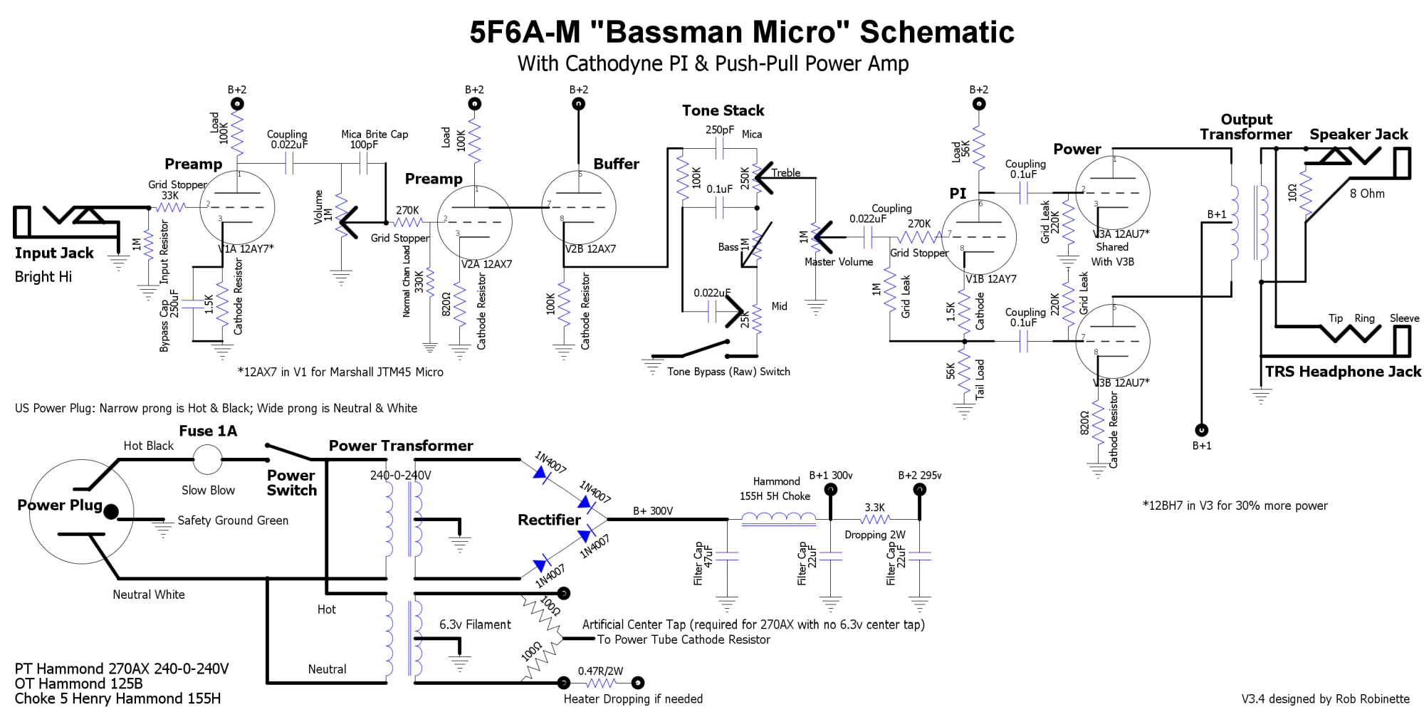
I'm beginning the design stage of my next project amp, the 5F6A-M Bassman Micro. It uses three 12A*7 tubes and features a cathodyne phase inverter and true push-pull 12AU7 or 12BH7 power tube.
Nice project Rob!! A friend and I were planning on exactly the same type of build. Very interesting. Seems that one of these could be a handy benchtop tube tester as well.
martin manning wrote:I figure that 1.2A at 6.3V on the secondary is 6.3/120*1.2 = 63mA on the primary ;^)
How do you calculate the entire load and select the appropriate sized fuse?
Tony
"Education is what you're left with after you have forgotten what you have learned" - Enzo
Same calculation for the required primary current for the current in each secondary winding, then add them up. That would be the absolute minimum amperage for the fuse in the primary. It will have to be increased to cover the start-up surge and full power vs. idle current, probably ~2x. In the end it's the smallest you can get away with.
Thanks Martin. I had never thought of the calculation you used to go through the TX like that. Never thought it could be that simple... that's why I asked.
I needs me some more book learnin'.
Tony
"Education is what you're left with after you have forgotten what you have learned" - Enzo
Can you explain to me the "Floating Ground" that you have for B+1 and V2's cathode bias?
I second the complement and the request for explanation of "Floating Ground."
TIA,
Gene
I don't see that at all. The drawing hasn't been edited from the above post. V3A had a shared cathode with V3B which are grounded and the B+1 filter cap is grouded as well... right? Also, I see cathode resistors connected to ground on both sides of V2... No?
Am I missing something?
Tony
Tony,
Please see the "layout" in the first post of the thread. Near the top left of the circuit board it says "Power Amp Floating Ground." I see what you are seeing on the schematic and this is the reason for asking for clarification. Curious as to whether something is implemented, but not shown. There is no mention of this "Floating Ground" on the schematic, but is referred to on the PTP diagram as well as layout.
Thank You,
Gene
Sorry about the discrepancy between the schematic and layout on the "floating ground." Instead of grounding the center taps to the chassis they are connected to the power tube cathode resistor and first filter cap 'ground' connections. It's an attempt to reduce chassis eddy currents. The preamp ground bus it grounded to the chassis at the input jack.
 656]http://robrobinette.com/images/Guitar/B ... _small.png[/img]
V3A had a shared cathode with V3B which are grounded and the B+1 filter cap is grouded as well... right? Also, I see cathode resistors connected to ground on both sides of V2... No?