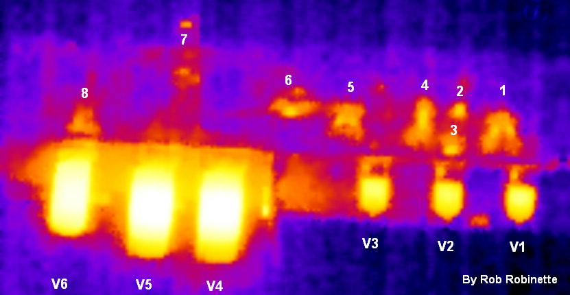
I have a Seek Thermal Imaging camera for my Android phone so I thought I'd take a pic of the 5F6A '59 Bassman chassis at idle temperature so we can see what's hot and what's not. I was surprised to see the power tubes are hotter than the rectifier tube.
[IMG:831:430]https://robrobinette.com/images/Guitar/ ... _Image.png[/img]
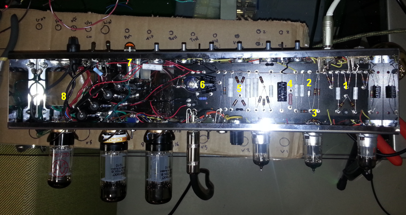
1. V1 Load Resistors. 2. V2B Cathode Resistor. 3. Socket mounted V2A Load Resistor. 4. B+4 Voltage Dropping Resistor. 5. Phase Inverter Load Resistors. 6. B+3 Voltage Dropping Resistor. 7. Pilot Light. 8. Rectifier Socket mounted Backup Diodes and .01uF 3KV disk capacitor.
[IMG:831:439]https://robrobinette.com/images/Guitar/ ... Image2.png[/img]
5F6A Bassman Thermal Image
Moderators: pompeiisneaks, Colossal

Re: 5F6A Bassman Thermal Image
I love it!
Looks like the amp was on a desk with tubes horizontal so heat would not rise into the chassis?
Very cool tool. I want that integrated into my heads-up display on my safety glasses.
Looks like the amp was on a desk with tubes horizontal so heat would not rise into the chassis?
Very cool tool. I want that integrated into my heads-up display on my safety glasses.
I build and repair tube amps. http://amps.monkeymatic.com
-
vibratoking
- Posts: 2640
- Joined: Tue Nov 10, 2009 9:55 pm
- Location: Colorado Springs, CO
Re: 5F6A Bassman Thermal Image
Very cool. It would be really nice to have a colormap so the actual temps could be correlated to the colors.
Electronic equipment is designed using facts and mathematics, not opinion and dogma.

Re: 5F6A Bassman Thermal Image
Are the power tube plates really hotter or is what you seeing really just the larger plate structure of the those tubes?. Ocassionally, when burning in a build I will use my Fluke IR gun to measure the temps of the OT tubes.robrob wrote:I have a Seek Thermal Imaging camera for my Android phone so I thought I'd take a pic of the 5F6A '59 Bassman chassis at idle temperature so we can see what's hot and what's not. I was surprised to see the power tubes are hotter than the rectifier tube.
[IMG:831:430]https://robrobinette.com/images/Guitar/ ... _Image.png[/img]
1. V1 Load Resistors. 2. V2B Cathode Resistor. 3. Socket mounted V2A Load Resistor. 4. B+4 Voltage Dropping Resistor. 5. Phase Inverter Load Resistors. 6. B+3 Voltage Dropping Resistor. 7. Pilot Light. 8. Rectifier Socket mounted Backup Diodes and .01uF 3KV disk capacitor.
[IMG:831:439]https://robrobinette.com/images/Guitar/ ... Image2.png[/img]
TM
Re: 5F6A Bassman Thermal Image
I'm just going by the larger and whiter white (hot) spots on the power tubes so it's a precision guesstimateAre the power tube plates really hotter or is what you seeing really just the larger plate structure of the those tubes?. Ocassionally, when burning in a build I will use my Fluke IR gun to measure the temps of the OT tubes.
Re: 5F6A Bassman Thermal Image
Yes. The shot is vertically downward into the chassis. I had to stand on a bar stool to get the camera high enough to get the whole chassis.Looks like the amp was on a desk with tubes horizontal so heat would not rise into the chassis?