Princeton tremolo minimum speed
Moderators: pompeiisneaks, Colossal

Princeton tremolo minimum speed
The Princeton Reverb tremolo circuit maximum speed is, I believe, dictated by the minimum resistance to ground on the tremolo rate pot (100K to ground). Does that mean the minimum speed is dictated by the rate pot value, in this case a 3M reverse log? I find the stock minimum Princeton tremolo rate to be faster than I’d like. I like it slow, man. Thanks.
Just plug it in, man.
-
martin manning

- Posts: 13372
- Joined: Sun Jul 06, 2008 12:43 am
- Location: 39°06' N 84°30' W
Re: Princeton tremolo minimum speed
A common mod to slow down the trem is increase the 0.01 cap next to the 0.02 to 0.02.
Re: Princeton tremolo minimum speed
The trem speed is determined by three caps and three resistors. A popular way to slow the speed is to replace the .01 cap that's connected to the speed pot with a .02 cap. I like to just use a switch to put another .01 in parallel with that cap.ViperDoc wrote: ↑Thu Oct 08, 2020 2:55 am The Princeton Reverb tremolo circuit maximum speed is, I believe, dictated by the minimum resistance to ground on the tremolo rate pot (100K to ground). Does that mean the minimum speed is dictated by the rate pot value, in this case a 3M reverse log? I find the stock minimum Princeton tremolo rate to be faster than I’d like. I like it slow, man. Thanks.
Re: Princeton tremolo minimum speed
Excellent. So a 0.02 uF in the middle. Very much appreciated, all! I like the parallel cap on a switch idea.
I read as much of Blencoe's tremolo oscillator section on valve wizard as I could briefly make sense of.
Here:
The frequency / rate control:
To vary the frequency of oscillation it is merely necessary to vary one or more of the filter components- usually the shunt resistors since variable capacitors are uncommon. To get even and predictable variation it would be necessary to vary all three resistors simultaneously by means of a ganged pot, but thankfully that level of accuracy is not required for tremolo. Fender tend to vary R1, while most Vox amps make R2 variable, and there is no reason why R3 couldn't be varied- it makes little difference, provided the loop gain is high to begin with. The practical range of frequencies is limited to a ratio of about 1:3 when using a single pot. The usual approach is to design the oscillator for a frequency that is midway between the highest and lowest desired frequency, then add a series limiting resistor to prevent the total shunt resistance being reduced to zero. Thus the frequency can then be varied both above and below the initial chosen frequency (increasing resistance causes decreasing frequency). It will usually be necessary to experiment with the value of this limiting resistor, in order to get the maximum range without oscillations actually stopping. The oscillator designs found in the classic amps use wildly varying component values, and were almost certainly chosen by experimentation rather than calculation.
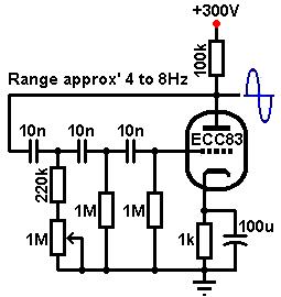
So this example suggests an oscillator designed around a range of 4-8 Hz. I would like to get down to around 2 Hz. He talks about "choosing the [median] frequency" as well as "experiment[ing] with the value of (the) limiting resistor in order to get the maximum range..."
I understand the 220K above the 1M pot to be the "limiting resistor" that determines the width of the oscillation range. How do you "choose the [median] frequency"???
I read as much of Blencoe's tremolo oscillator section on valve wizard as I could briefly make sense of.
Here:
The frequency / rate control:
To vary the frequency of oscillation it is merely necessary to vary one or more of the filter components- usually the shunt resistors since variable capacitors are uncommon. To get even and predictable variation it would be necessary to vary all three resistors simultaneously by means of a ganged pot, but thankfully that level of accuracy is not required for tremolo. Fender tend to vary R1, while most Vox amps make R2 variable, and there is no reason why R3 couldn't be varied- it makes little difference, provided the loop gain is high to begin with. The practical range of frequencies is limited to a ratio of about 1:3 when using a single pot. The usual approach is to design the oscillator for a frequency that is midway between the highest and lowest desired frequency, then add a series limiting resistor to prevent the total shunt resistance being reduced to zero. Thus the frequency can then be varied both above and below the initial chosen frequency (increasing resistance causes decreasing frequency). It will usually be necessary to experiment with the value of this limiting resistor, in order to get the maximum range without oscillations actually stopping. The oscillator designs found in the classic amps use wildly varying component values, and were almost certainly chosen by experimentation rather than calculation.
So this example suggests an oscillator designed around a range of 4-8 Hz. I would like to get down to around 2 Hz. He talks about "choosing the [median] frequency" as well as "experiment[ing] with the value of (the) limiting resistor in order to get the maximum range..."
I understand the 220K above the 1M pot to be the "limiting resistor" that determines the width of the oscillation range. How do you "choose the [median] frequency"???
Just plug it in, man.