Adding Framus Mid Scoop EQ to 5F1 Clone

Fender Amp Discussion

Moderators: pompeiisneaks, Colossal

Post Reply
User avatar
Gregg Hermetech
Posts: 21
Joined: Tue Jul 18, 2023 2:16 pm
Location: Milan, Italy
Contact:

Adding Framus Mid Scoop EQ to 5F1 Clone

Post by Gregg Hermetech »

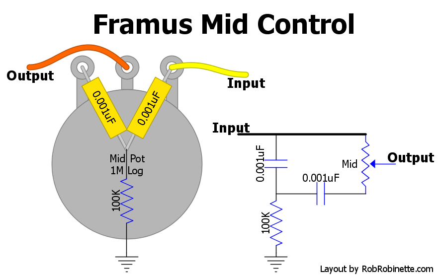
I want to add this fairly simple looking Framus Mid (and slight Bass) Scoop EQ control to my 5F1 clone. It should allow a bit more of a Blackface sound, and because I do a lot of Funk strumming recently, it'd be great to be able to rip out some low end and mids. Here is my amp schematic:
Schematic.png
RR has a bit about it here:

https://robrobinette.com/Generic_Tube_A ... id_Control

Image

And these are the values I intend on using:

https://www.guitarscience.net/tsc/framu ... pot=Linear

I'm going with a 68k fixed resistor instead of 100k because it seems you get a bit more attenuation, and at a slightly higher frequency.

I have a load of questions about this one, but will put them in separate posts below.

For now, I just want to say thanks for all the great information on this forum. I'm a total beginner but people have gone out of their way to be very helpful and I owe you all a beer! 8)
You do not have the required permissions to view the files attached to this post.
Last edited by Gregg Hermetech on Thu Oct 19, 2023 9:16 am, edited 2 times in total.
https://musicwall.app/hermetech
User avatar
Gregg Hermetech
Posts: 21
Joined: Tue Jul 18, 2023 2:16 pm
Location: Milan, Italy
Contact:

Re: Adding Framus Mid Scoop EQ to 5F1 Clone

Post by Gregg Hermetech »

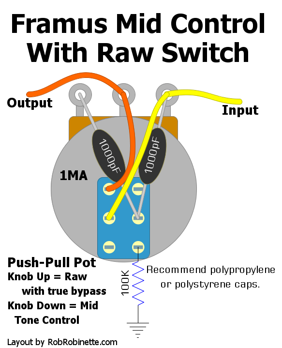
1) The online TSC shows that with the pot at 10, nothing happens, it's like NOT having the EQ in the circuit. Will this actually be the case? What would the insertion loss of those components likely be, either in level, or frequency response? I ask because RR also shows a version with a switched pot, so that when switched, the extra components are totally bypassed:

Image

I currently only have a regular 1M Log pot but now I'm worried that it might change the sound of the amp too much, even when set to minimum attenuation. Happy to try and find the switched version of the pot if you guys think it would be worth it. I don't want to start soldering components to the back of the pot until I know this.
https://musicwall.app/hermetech
User avatar
Gregg Hermetech
Posts: 21
Joined: Tue Jul 18, 2023 2:16 pm
Location: Milan, Italy
Contact:

Re: Adding Framus Mid Scoop EQ to 5F1 Clone

Post by Gregg Hermetech »

2) Where exactly in the amp schematic would it be wisest to fit this pot? (See schematic in original post). Between the C1 coupling cap and the Volume control VR1, or directly after VR1? Or later in the circuit directly after the C2 coupling cap before the power stage?
https://musicwall.app/hermetech
User avatar
Gregg Hermetech
Posts: 21
Joined: Tue Jul 18, 2023 2:16 pm
Location: Milan, Italy
Contact:

Re: Adding Framus Mid Scoop EQ to 5F1 Clone

Post by Gregg Hermetech »

3) The online TSC shows that with the pot at minimum you have maximum attenuation of frequencies, and with the pot at maximum you essentially have it bypassed/zero attenuation. I'd like it to be the opposite way round. i.e. pot at minimum = no effect, pot at maximum = most effect. Is this possible, and if so how?
https://musicwall.app/hermetech
User avatar
martin manning
Posts: 13208
Joined: Sun Jul 06, 2008 12:43 am
Location: 39°06' N 84°30' W

Re: Adding Framus Mid Scoop EQ to 5F1 Clone

Post by martin manning »

I think you will get some interesting results with this in the Champ circuit. I played around with some values and landed on what you see below to put the scoop at 400Hz. Of course you should experiment a bit for yourself. For that purpose, get a 1/2W resistor kit from Amazon or eBay so you have a range of values on hand to try, and get a handful of 500-600V caps in common values (a couple of each from 1n to 100n film, and 50p to 820p ceramic or mica).
Gregg Hermetech wrote: Thu Oct 19, 2023 9:14 am 1) The online TSC shows that with the pot at 10, nothing happens, it's like NOT having the EQ in the circuit. Will this actually be the case? What would the insertion loss of those components likely be, either in level, or frequency response?
An isolated simulation as in TSC lacks context and therefore misses interactions with adjacent components. You will lose some highs above 1k. Lifting the resistor to ground will eliminate that, but shorting the pot and lifting the resistor with a DPDP pull switch pot would allow keeping a setting and switching it in and out.
Gregg Hermetech wrote: Thu Oct 19, 2023 9:15 am 2) Where exactly in the amp schematic would it be wisest to fit this pot? (See schematic in original post). Between the C1 coupling cap and the Volume control VR1, or directly after VR1? Or later in the circuit directly after the C2 coupling cap before the power stage?
I'd go with placing it after the volume pot output as shown below.
Gregg Hermetech wrote: Thu Oct 19, 2023 9:15 am 3) The online TSC shows that with the pot at minimum you have maximum attenuation of frequencies, and with the pot at maximum you essentially have it bypassed/zero attenuation. I'd like it to be the opposite way round. i.e. pot at minimum = no effect, pot at maximum = most effect. Is this possible, and if so how?
Connect the CCW terminal of the pot to the volume pot wiper and then CW rotation will bring on the mid scoop. An audio or linear pot will work for this, but IMO the best option would be a 30% J-taper pot.
You do not have the required permissions to view the files attached to this post.
User avatar
Gregg Hermetech
Posts: 21
Joined: Tue Jul 18, 2023 2:16 pm
Location: Milan, Italy
Contact:

Re: Adding Framus Mid Scoop EQ to 5F1 Clone

Post by Gregg Hermetech »

Thank you for the in-depth answer Martin. It's a darkish sounding amp anyway, so I'd hate to lose any more high end. I'll try and hunt down the pull switched pot.
https://musicwall.app/hermetech
Post Reply