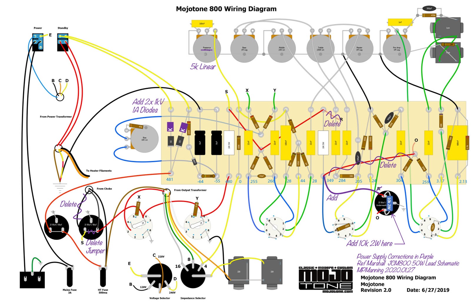
See here: https://drtube.com/library/schematics/6 ... mas#JCM800 under 1987 JCM800 Lead, 50W head. Steve is right, there are two versions, but I can't see the screens needing 100u, and splitting that cap puts one dual triode on each node. It may be that the one showing 100u on the screen is in error, as actual examples don't seem to be configured like that.
Yes, I am saying keep the "S" lead as shown to put that 10k between the two 50u sections.
Channel Switching JCM800 Design? + BIAS pot question
Moderators: pompeiisneaks, Colossal
-
martin manning

- Posts: 13296
- Joined: Sun Jul 06, 2008 12:43 am
- Location: 39°06' N 84°30' W
1 others liked this
-
sluckey
- Posts: 3099
- Joined: Sun Jul 22, 2007 7:48 pm
- Location: Mobile, AL
- Contact:
1 others liked this
Re: Channel Switching JCM800 Design? + BIAS pot question
I agree. As long as you snip that jumper on the can and move the choke lead to the right cap as you showed in the corrected drawing.Yes, I am saying keep the "S" lead as shown to put that 10k between the two 50u sections.

Re: Channel Switching JCM800 Design? + BIAS pot question
Mods complete:martin manning wrote: ↑Wed Jan 29, 2020 12:34 am See here: https://drtube.com/library/schematics/6 ... mas#JCM800 under 1987 JCM800 Lead, 50W head. Steve is right, there are two versions, but I can't see the screens needing 100u, and splitting that cap puts one dual triode on each node. It may be that the one showing 100u on the screen is in error, as actual examples don't seem to be configured like that.
Yes, I am saying keep the "S" lead as shown to put that 10k between the two 50u sections.
Additional turrets and diodes added.
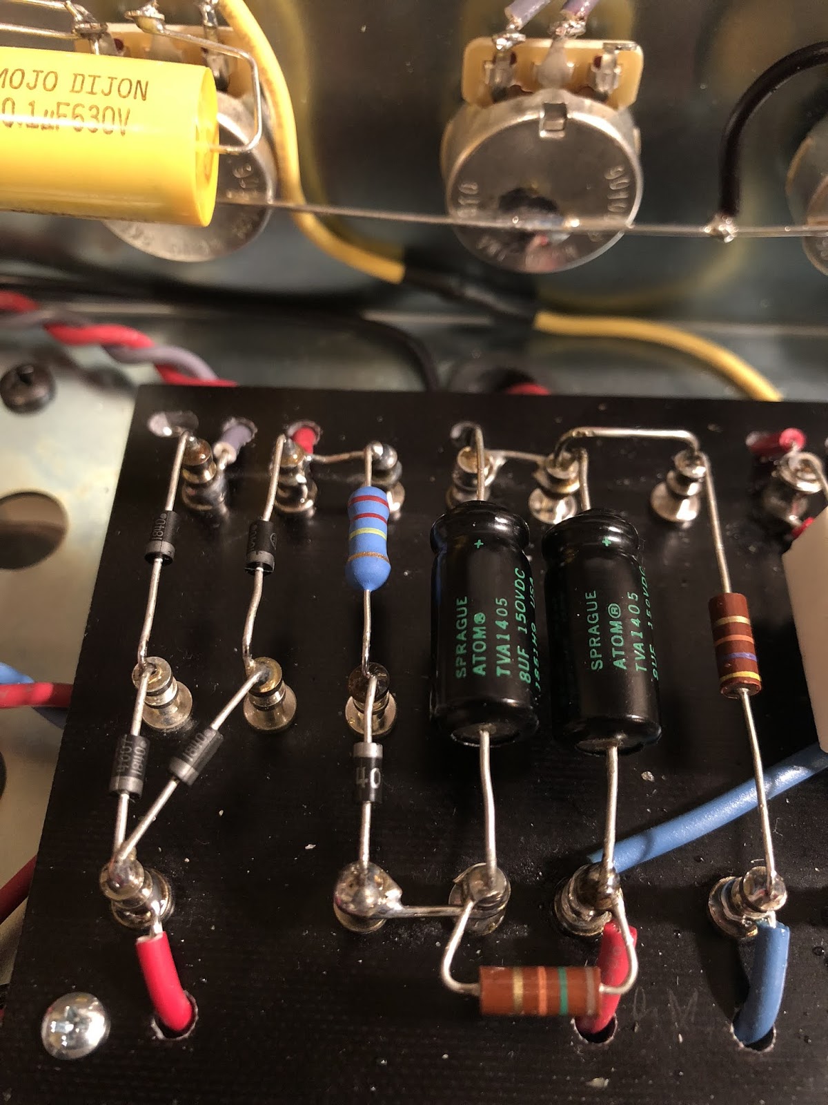
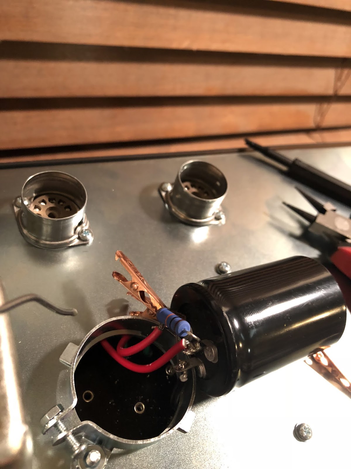
Preamp Can Cap removed and 10K 2W resistor added.
Incorrect wires deleted. Can + terminal wire re-routed.
5K Linear Presence pot confirmed. The diagram says "5K Log" but the pot, I believe is linear by the "L" designation.
Now all I have to do is wait for the correct 1K 5W ceramic screen resistors to get here so I can swap the incorrect ones out. I thought I would clip the output transformer pin 3 wires in place to test for feedback during power up before I solder them in.
You guys are awesome. Thank you for your help!
Just plug it in, man.
-
martin manning
- Posts: 13296
- Joined: Sun Jul 06, 2008 12:43 am
- Location: 39°06' N 84°30' W
Re: Channel Switching JCM800 Design? + BIAS pot question
Set it at 50% and measure resistance to ground from the CW lug and the middle lug. If the middle is ~half of the CW, it's linear.
I'd leave them long enough that you could reverse them if necessary, and just tack solder them in place for the first start-up. You don't want those clips slipping off, or accidentally touching anything else.
Note that in both versions of the power supply rail seen in the Marshall 2204 schematics V1 and V2 are decoupled, and the same is true on the Mojo schematic. However, Mojo's layout does not match their schematic in that regard.
Re: Channel Switching JCM800 Design? + BIAS pot question
Advice taken. Thanks!martin manning wrote: ↑Wed Jan 29, 2020 11:45 amSet it at 50% and measure resistance to ground from the CW lug and the middle lug. If the middle is ~half of the CW, it's linear.I'd leave them long enough that you could reverse them if necessary, and just tack solder them in place for the first start-up. You don't want those clips slipping off, or accidentally touching anything else.
Note that in both versions of the power supply rail seen in the Marshall 2204 schematics V1 and V2 are decoupled, and the same is true on the Mojo schematic. However, Mojo's layout does not match their schematic in that regard.
When you say decoupled, are you referring to the 10K cap across the can cap terminals?
Just plug it in, man.
-
martin manning
- Posts: 13296
- Joined: Sun Jul 06, 2008 12:43 am
- Location: 39°06' N 84°30' W
1 others liked this
Re: Channel Switching JCM800 Design? + BIAS pot question
Yes the RC combination prevents signal from flowing back upstream through the power rail.
Re: Channel Switching JCM800 Design? STARTED UP 1.0
OK. I started up the amp. Here's what happened:
1) Power on w/o tubes and checked filaments--all OK, but the light on the power switch does not go on. WTF.
2) Power on with preamp tubes--all OK, higher VDC readings as expected
3) Power on with all tubes--POSITIVE FEEDBACK. So I switched the OT red and white wires after powering down and draining the caps. Then, no PFB.
4) I powered on with all tubes and got the following voltages in Blue on the diagram:
How does this look to you?
I plugged a guitar in and turned the knobs. GD is this thing noisy. Squealing as I turn up the eq knobs. I go into the low input and I can play guitar, that's for sure, but there are odd sounds as I turn the knobs and volume up.
Obviously, there's something wrong, but [REDACTED].
Last edited by ViperDoc on Wed Feb 05, 2020 6:04 am, edited 1 time in total.
Just plug it in, man.
Re: Channel Switching JCM800 Design? + BIAS pot question
All right, so I had a bad attitude. I plugged into the JTM45 I just built and DAMN does that thing sound good. I mean REALLY GOOD. I want this thing to sound good, too!
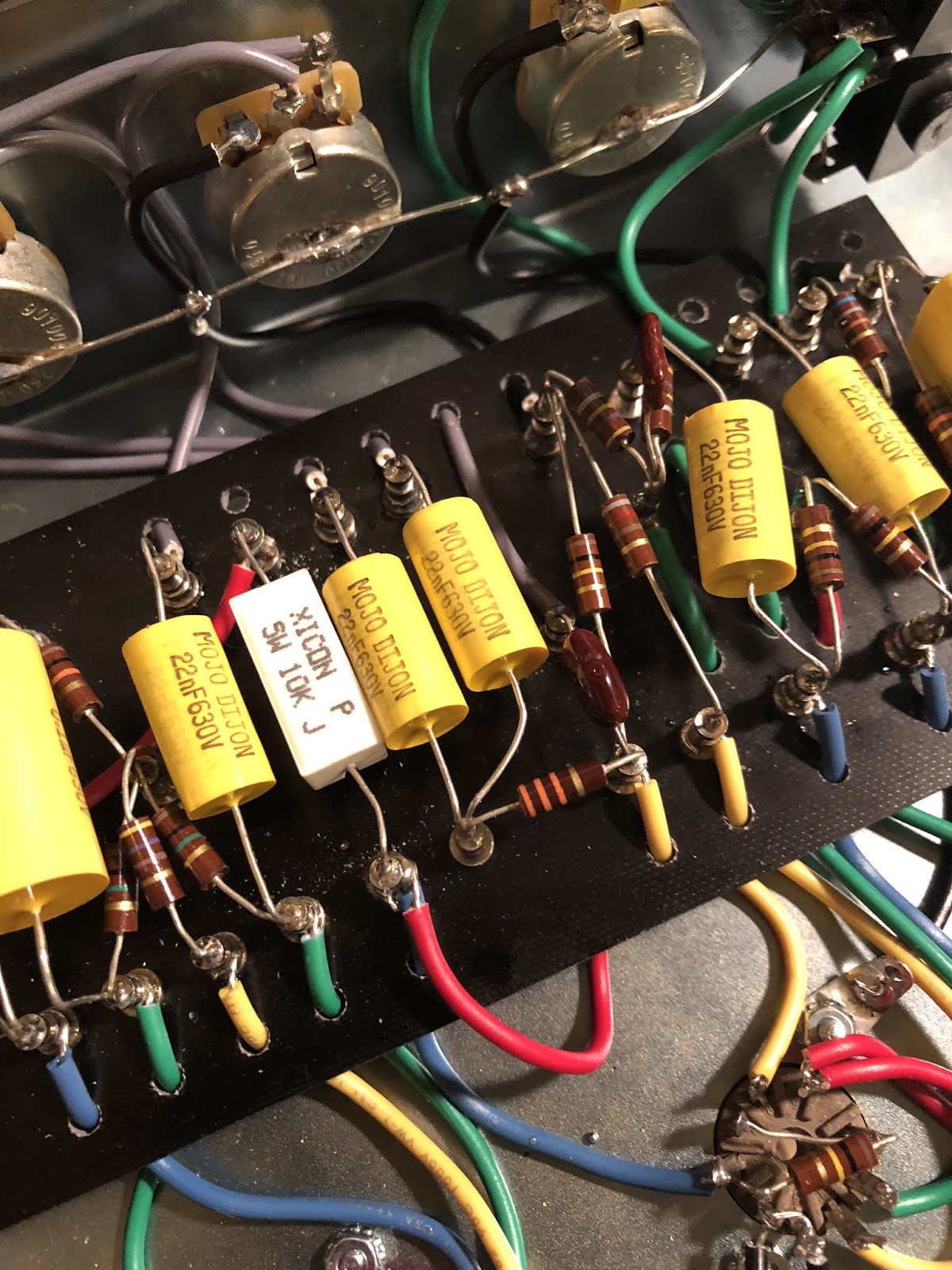
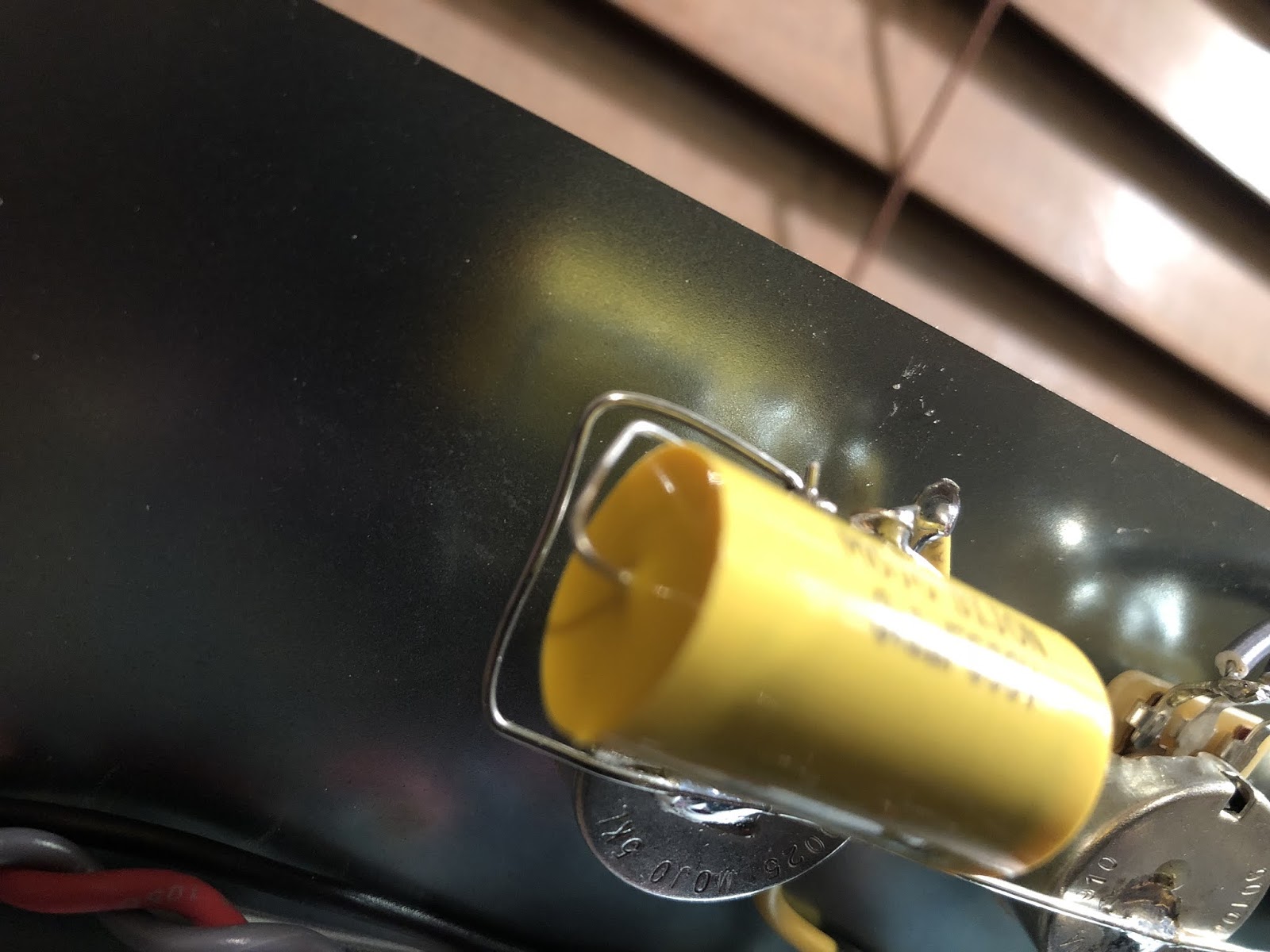
BODY SHOTS!
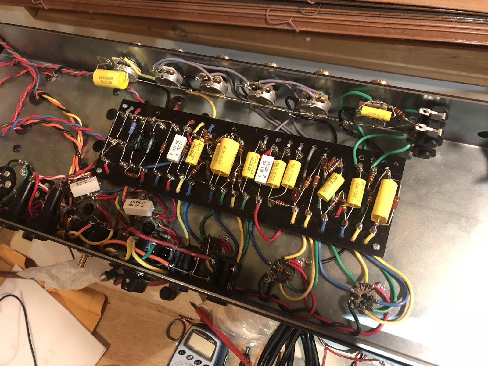
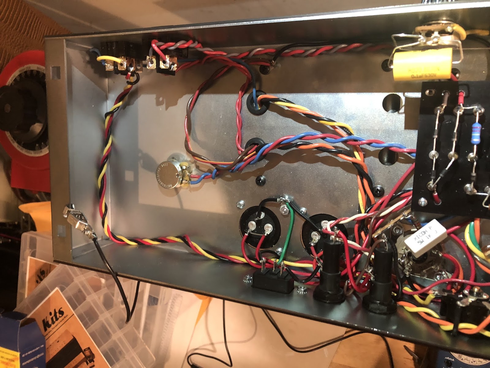
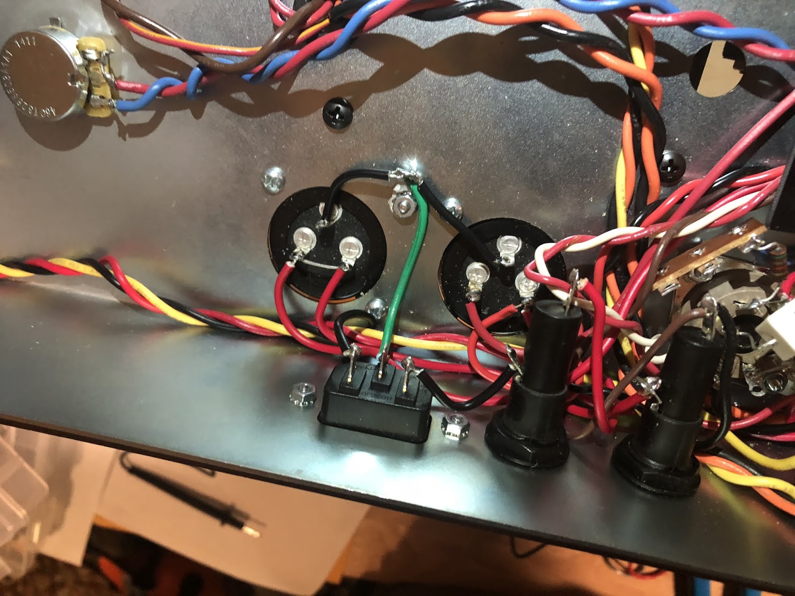
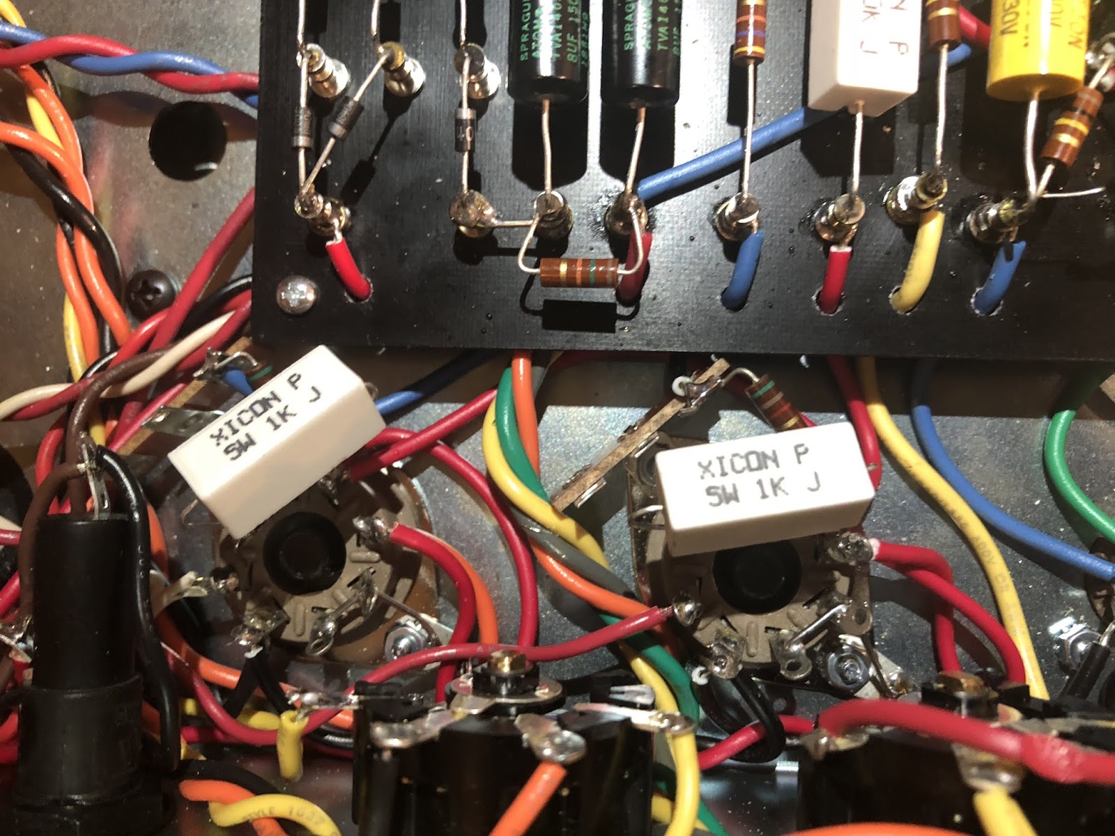
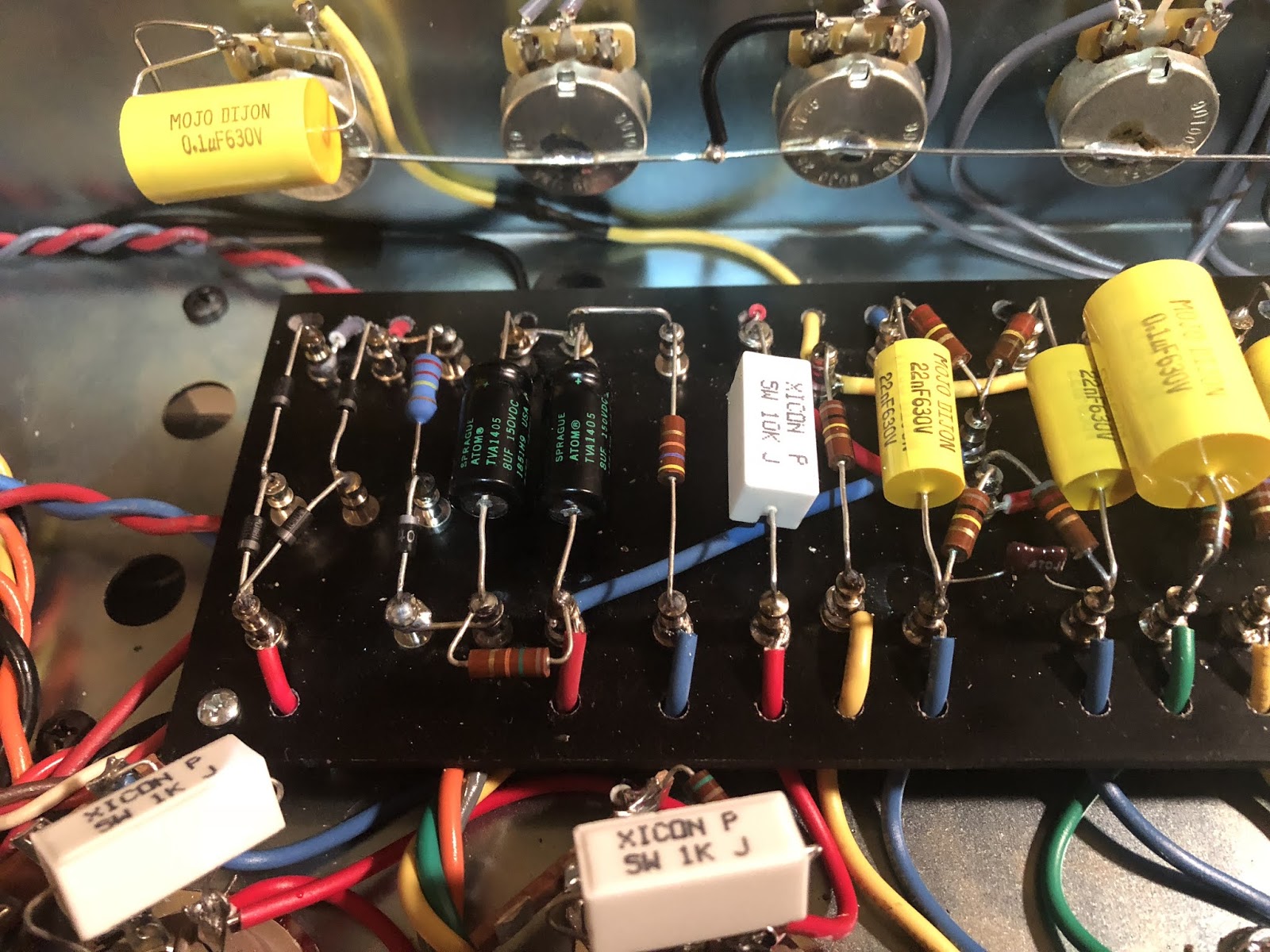
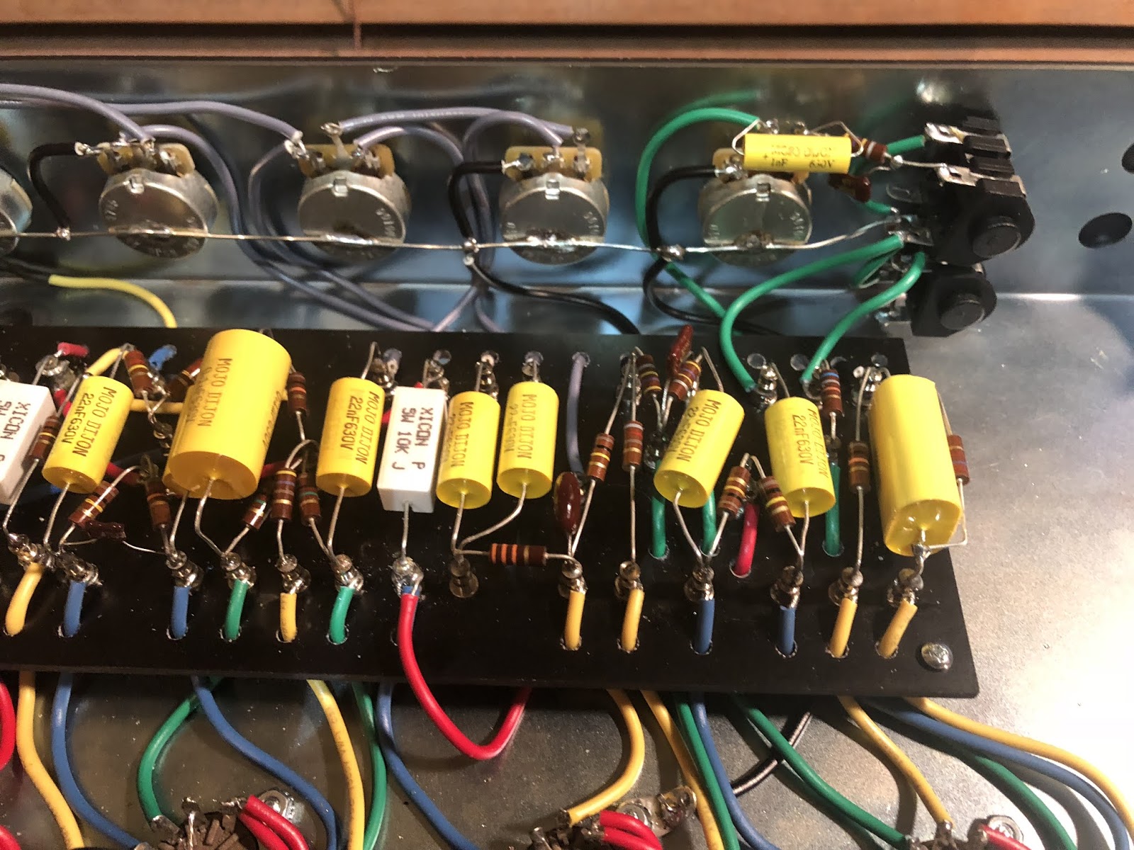
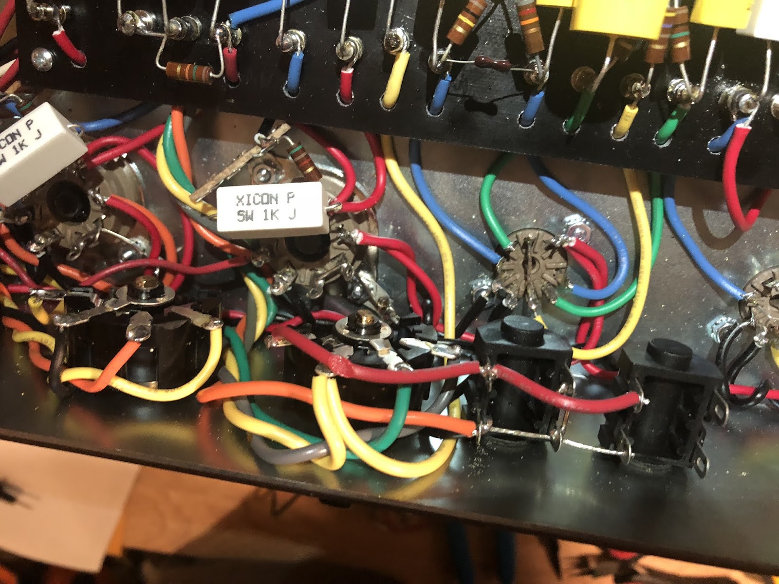
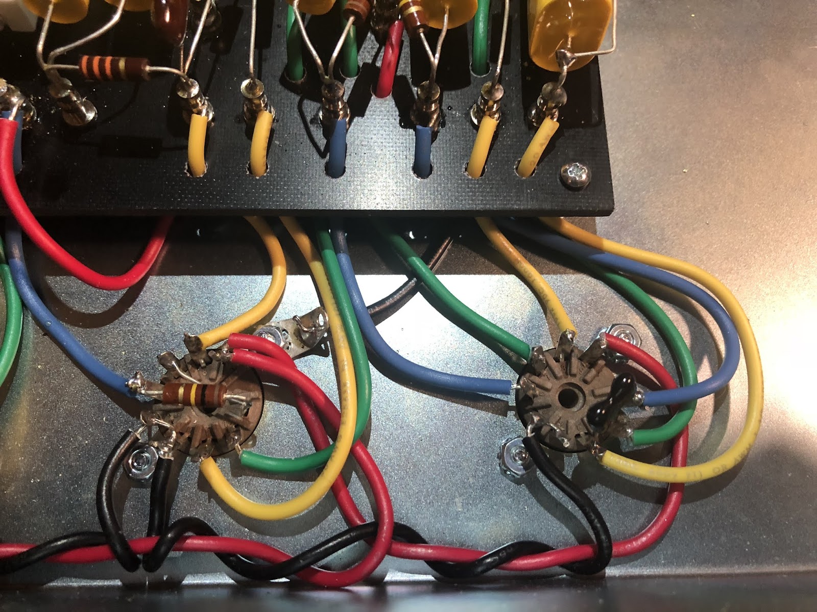
Things to note:
1) overheated speaker jack wire.
2) the output jacks are wired unlike anything I've ever seen before. Others just run them straight through.
3) wire soup under the voltage selector--not sure why I would even need that, seems a waste of space.
4) some long wires owing to the 29-inch chassis and no-room-for-even-the-bias-pot-that-is-included. No idea why they ever made the chassis this big.
5) the noises coming from the amp sound like UFO swells, sine wave type of stuff.
Where to go from here...
BODY SHOTS!
Things to note:
1) overheated speaker jack wire.
2) the output jacks are wired unlike anything I've ever seen before. Others just run them straight through.
3) wire soup under the voltage selector--not sure why I would even need that, seems a waste of space.
4) some long wires owing to the 29-inch chassis and no-room-for-even-the-bias-pot-that-is-included. No idea why they ever made the chassis this big.
5) the noises coming from the amp sound like UFO swells, sine wave type of stuff.
Where to go from here...
Just plug it in, man.
Re: Channel Switching JCM800 Design? + IT WORKS!!!!
YES!!!!!
THE 800 AMP SOUNDS INSANE!!!!!
I took a breather, chopsticked it, moved some wires around, made some adjustments to the input jacks and VOILA!!!
I apologize if you read my disappointing post and felt underpaid for your babysitting, it likely parallels what I was feeling at that moment--I had a lot to deal with over the weekend and I really wanted this thing to sound good when I got home, and it didn't. Well, it does now. I wish I could explain it, but all the UFO sound is replaced by chunky, snarling British rock tone, man! YES!!!!!! WHOOOOOOOOHOOOOOO!!!!!
THANK YOU GUYS FOR HELPING ME, YOU REALLY MADE THIS WHAT IT IS WITH ALL THE LAYOUT MODS AND IMPROVEMENTS. THIS AMP SOUNDS AWESOME.
*NOW* TO MY ORIGINAL QUESTION, WHEN THE TIME IS RIGHT: How do you make something like a channel switching British rock amp where you have, say, individual gains and a shared master volume or even dual gain's and masters with a shared tone stack? I thought back to the TMD design where you have individual inputs, it seems you could just switch between those with a foot pedal.
Anyway, THANK YOU!!!
Just plug it in, man.
-
martin manning
- Posts: 13296
- Joined: Sun Jul 06, 2008 12:43 am
- Location: 39°06' N 84°30' W
1 others liked this
Re: Channel Switching JCM800 Design? + BIAS pot question
Always fun to experience a new one coming to life! It's not uncommon to have one or two things wrong, with the initial result being bad sound or no sound at all. You just have to work through it. I'd guess a bad solder joint somewhere that got fixed in the process. Glad you got it solved.
-
pompeiisneaks

- Site Admin
- Posts: 4222
- Joined: Sat Jan 14, 2017 4:36 pm
- Location: Washington State, USA
- Contact:
1 others liked this
Re: Channel Switching JCM800 Design? + BIAS pot question
Great News!
As for simple switching, yes what you want with a single input is possible. I built one of Sluckey's Dual Marshalls which has both the preamp for a plexi and a 2203/2204 in it, and it's foot switchable. If you look at that layout/schematic you can see his just used a switch but adding a relay to it via a footswitch/panel switch combo is pretty easy as well. See here on my thread about that: https://ampgarage.com/forum/viewtopic.p ... l+marshall
~Phil
tUber Nerd!
-
Colossal

- Posts: 5050
- Joined: Sat Oct 20, 2007 9:04 pm
- Location: Moving through Kashmir
1 others liked this
Re: Channel Switching JCM800 Design? + BIAS pot question
Excellent news, 'Doc,
"Lead dress", or the physical placement and routing of wires is an important consideration in tube amp building!
"Lead dress", or the physical placement and routing of wires is an important consideration in tube amp building!
Re: Channel Switching JCM800 Design? + BIAS pot question
That dual Marshall looks mental!pompeiisneaks wrote: ↑Wed Feb 05, 2020 4:33 pm Great News!
As for simple switching, yes what you want with a single input is possible. I built one of Sluckey's Dual Marshalls which has both the preamp for a plexi and a 2203/2204 in it, and it's foot switchable. If you look at that layout/schematic you can see his just used a switch but adding a relay to it via a footswitch/panel switch combo is pretty easy as well. See here on my thread about that: https://ampgarage.com/forum/viewtopic.p ... l+marshall
~Phil
Just plug it in, man.
Re: Channel Switching JCM800 Design? + BIAS pot question
Noted! Time to invest in some zip ties, I think.
Just plug it in, man.
-
martin manning
- Posts: 13296
- Joined: Sun Jul 06, 2008 12:43 am
- Location: 39°06' N 84°30' W
Re: Channel Switching JCM800 Design? + BIAS pot question
When you measured the voltages above (as noted on the layout) where was the power tube bias set, current-wise?