HOW DOES THE MOJO 18 W TMD LAYOUT LOOK TO YOU? EXPERT OPINIONS NEEDED.
Moderators: pompeiisneaks, Colossal

Re: HOW DOES THE MOJO 18 W TMD LAYOUT LOOK TO YOU? EXPERT OPINIONS NEEDED.
I guess there’s just one way to find out! Reading a bit about starved gain stages is interesting. Seems to be a popular idea for overdrive pedals. I don’t see a reason to have so much gain in a preamp that I can’t use the master volume, so once I finish my 2204, I’ll do this mod and report. Thanks for the work up!
Just plug it in, man.
Re: HOW DOES THE MOJO 18 W TMD LAYOUT LOOK TO YOU? EXPERT OPINIONS NEEDED.
Got it, that does look simple. Thanks! I’ll check that out as well.sluckey wrote: ↑Sat Feb 01, 2020 2:17 pm I may have jumped the gun on suggesting to change the mojo hi-gain preamp to the plexi style preamp. If you really like the mojo as is except for the hiss and screaming, then try this very simple mod. Add a 470K and optional 470pf (500pf) in series with the top of the volume control. The real JCM-800 2204 has this to tame gain a bit. I believe the mojo circuit would benefit from having these components also, and still maintain that hi-gain overdrive. It's a 5 minute mod, very easy to do, and easy to undo. Take a look.
Just plug it in, man.
Re: HOW DOES THE MOJO 18 W TMD LAYOUT LOOK TO YOU? EXPERT OPINIONS NEEDED.
That’s the same 470K and 500 pF you removed from the previous drawing that originally looked like it went from V2 to ground. Convenient!sluckey wrote: ↑Sat Feb 01, 2020 2:17 pm I may have jumped the gun on suggesting to change the mojo hi-gain preamp to the plexi style preamp. If you really like the mojo as is except for the hiss and screaming, then try this very simple mod. Add a 470K and optional 470pf (500pf) in series with the top of the volume control. The real JCM-800 2204 has this to tame gain a bit. I believe the mojo circuit would benefit from having these components also, and still maintain that hi-gain overdrive. It's a 5 minute mod, very easy to do, and easy to undo. Take a look.
Just plug it in, man.
Re: HOW DOES THE MOJO 18 W TMD LAYOUT LOOK TO YOU? EXPERT OPINIONS NEEDED.
No it's not. Don't confuse that second drawing with the first drawing.
1. The first drawing shows how to convert the mojo preamp to a plexi preamp. HOLD OFF ON THIS FOR NOW!
2. The second drawing shows how to add two components to tame the mojo preamp to be like the real JCM-800 2204 preamp. DO THIS FIRST SINCE IT'S SO EASY! If that doesn't make the mojo more usable then undo number 2. Then do number 1.
DO ONE OR THE OTHER, NOT BOTH!
Re: HOW DOES THE MOJO 18 W TMD LAYOUT LOOK TO YOU? EXPERT OPINIONS NEEDED.
Thanks, Sluckey!sluckey wrote: ↑Sun Feb 02, 2020 11:26 amNo it's not. Don't confuse that second drawing with the first drawing.
1. The first drawing shows how to convert the mojo preamp to a plexi preamp. HOLD OFF ON THIS FOR NOW!
2. The second drawing shows how to add two components to tame the mojo preamp to be like the real JCM-800 2204 preamp. DO THIS FIRST SINCE IT'S SO EASY! If that doesn't make the mojo more usable then undo number 2. Then do number 1.
DO ONE OR THE OTHER, NOT BOTH!
Just plug it in, man.
-
Governator
- Posts: 42
- Joined: Mon Feb 10, 2020 3:13 am
Re: HOW DOES THE MOJO 18 W TMD LAYOUT LOOK TO YOU? EXPERT OPINIONS NEEDED.
Hi, just seeing if you’ve had a chance to do the mod, if so did it make an improvement?
I’ve just finished the Mojo 18W TMB build as well and have the same issues - hiss that is too much on the TMB channel with gain maxed and master past about 4. I used shielded cable on both channels between jack input and tube, as well as between the gain pot and board, also changed the grid stoppers to metal film and mounted at the tubes on both channels, revised the earthing with a seperate power amp ground and pre amp ground, made careful attention to lead dress. Still getting plenty of hiss so might give this a try, not too worried about loosing some gain, if i want more i can boat it with my OCD I guess. Let us know how you went!
I’ve just finished the Mojo 18W TMB build as well and have the same issues - hiss that is too much on the TMB channel with gain maxed and master past about 4. I used shielded cable on both channels between jack input and tube, as well as between the gain pot and board, also changed the grid stoppers to metal film and mounted at the tubes on both channels, revised the earthing with a seperate power amp ground and pre amp ground, made careful attention to lead dress. Still getting plenty of hiss so might give this a try, not too worried about loosing some gain, if i want more i can boat it with my OCD I guess. Let us know how you went!
Re: HOW DOES THE MOJO 18 W TMD LAYOUT LOOK TO YOU? EXPERT OPINIONS NEEDED.
Hi Governator, I still have my 800 channel on the bench, so I haven't done the TMB mods. I'm waiting for the parts to arrive and will do one then the other depending on the results. Strange to have so much noise, it makes the TMB's gain channel unusable at high volumes. I'll report when I work on it.Governator wrote: ↑Mon Feb 10, 2020 8:15 am Hi, just seeing if you’ve had a chance to do the mod, if so did it make an improvement?
I’ve just finished the Mojo 18W TMB build as well and have the same issues - hiss that is too much on the TMB channel with gain maxed and master past about 4. I used shielded cable on both channels between jack input and tube, as well as between the gain pot and board, also changed the grid stoppers to metal film and mounted at the tubes on both channels, revised the earthing with a seperate power amp ground and pre amp ground, made careful attention to lead dress. Still getting plenty of hiss so might give this a try, not too worried about loosing some gain, if i want more i can boat it with my OCD I guess. Let us know how you went!
Just plug it in, man.
-
Governator
- Posts: 42
- Joined: Mon Feb 10, 2020 3:13 am
Re: HOW DOES THE MOJO 18 W TMD LAYOUT LOOK TO YOU? EXPERT OPINIONS NEEDED.
Hi mate, I tried the above mod over the weekend - I had some 470k 1/2w and 500p spare so gave it a go. I think it has made a small difference with reducing some hiss, may have cut some of the low end (hard to really tell without directly AB’ing it). I did think about putting a switch across the 470k/500p to short it out as a way to A/B it, but this will probably introduce more noise/hiss in itself.
I think I’ll just leave it as is now, see below pic, there was an empty turret next to the 22nF where the TMB 470K grid stopper resistor was originally mounted but moved to some tag strip at the tube to reduce noise. It worked out quite well, if I ever want to revert back, it’s as simple as replacing the 470K/500p with a bridge.
I think I’ll just leave it as is now, see below pic, there was an empty turret next to the 22nF where the TMB 470K grid stopper resistor was originally mounted but moved to some tag strip at the tube to reduce noise. It worked out quite well, if I ever want to revert back, it’s as simple as replacing the 470K/500p with a bridge.
You do not have the required permissions to view the files attached to this post.
Re: HOW DOES THE MOJO 18 W TMD LAYOUT LOOK TO YOU? EXPERT OPINIONS NEEDED.
Thanks for the report! I’ll let you know how mine turns out.
Just plug it in, man.
Re: HOW DOES THE MOJO 18 W TMD LAYOUT LOOK TO YOU? EXPERT OPINIONS NEEDED.
I would think think that swapping those carbon comp resistors in the preamp stages for carbon film, or better yet, metal film would help to alleviate some of the hiss.
-
Governator
- Posts: 42
- Joined: Mon Feb 10, 2020 3:13 am
Re: HOW DOES THE MOJO 18 W TMD LAYOUT LOOK TO YOU? EXPERT OPINIONS NEEDED.
Yeah I did think about swapping out some of the CC resistors and see if that made a difference.
I was bored the other day and ended up putting a switch across the 470k/500p described above, wired with shielded cable earthed at one end only. The switch just shorts out this in the ON position. It does reduce the gain and the hiss a little bit, looses some “balls”. I’m really tempted to do the other mod described above to a plexi-like cathode driven tone stack like, i’m in two minds about doing this one. Let us know how you go if you end up trying any of these on yours. Cheers
I was bored the other day and ended up putting a switch across the 470k/500p described above, wired with shielded cable earthed at one end only. The switch just shorts out this in the ON position. It does reduce the gain and the hiss a little bit, looses some “balls”. I’m really tempted to do the other mod described above to a plexi-like cathode driven tone stack like, i’m in two minds about doing this one. Let us know how you go if you end up trying any of these on yours. Cheers
You do not have the required permissions to view the files attached to this post.
Re: HOW DOES THE MOJO 18 W TMD LAYOUT LOOK TO YOU? EXPERT OPINIONS NEEDED.
YO, SLUCKEY, YOU ARE THE MAN.
You gave me two ways to tame the 18 watt Mojo TMB, so I did them in the order you suggested. I inserted the 470K/500pF components in series after the 22nF cap you highlighted first. It sounded much better at lower volumes and kept the high gain sound intact. At higher master volume settings, the howling was still present. So I reversed that back to normal and proceeded with the cathode follower mod as below:
I turned this baby on and WOW. The gain is lower, but it is so much more usable. At higher gain settings, it sounds great, too. I don't know why I would need more gain than this. Awesome, man!
Now I have questions just so I can understand this stuff better:
1) I notice when the TMB gain or master volume are turned up while playing, there is a certain high-pitched fizzle to the distortion. I tried two different 212 cabs with the same results. When I stop playing, the amp is dead silent. How would I get rid of that fizzle?
2) You jumpered the V2B cathode wire to the tone slope resistor and thereby connected the 100K V2B cathode resistor, tone slope resistor and 500 pF treble cap on the same node. Is that right? [EDIT: THAT IS THE CATHODE FOLLOWER, JUST AS YOU SAID. GOT IT! I GOT CONFUSED BECAUSE THAT WIRE COMES OFF OF PIN 3--I THOUGHT PIN 3 WAS ALWAYS THE "A" SIDE OF THE 12AX7, BUT PERHAPS THE CIRCUIT ITSELF DIRECTS THAT?]
3) The TMB mid control is now *very* subtle. It could have always been that way, I don't recall. Not that you would need to change it, really, because it sounds great!
4) When I turn up the TMB master to full volume, I don't get the massive screeching anymore, but I can entertain some high gain feedback like the kind you don't mind hearing in rock and roll. MISSION ACCOMPLISHED.
Sluckey, sir, thank you for your time and effort in helping me with this mod. I see you helping others regularly as well, and I hope you get the acknowledgment and reward you deserve for all of that. You are much appreciated.
Cheers!
Just plug it in, man.
-
sluckey
- Posts: 3079
- Joined: Sun Jul 22, 2007 7:48 pm
- Location: Mobile, AL
- Contact:
1 others liked this
Re: HOW DOES THE MOJO 18 W TMD LAYOUT LOOK TO YOU? EXPERT OPINIONS NEEDED.
Glad you're liking it.
Fizz... That 47pF is supposed to help eliminate fizz and high freq oscillation. Change it to 100pF and see if that helps.
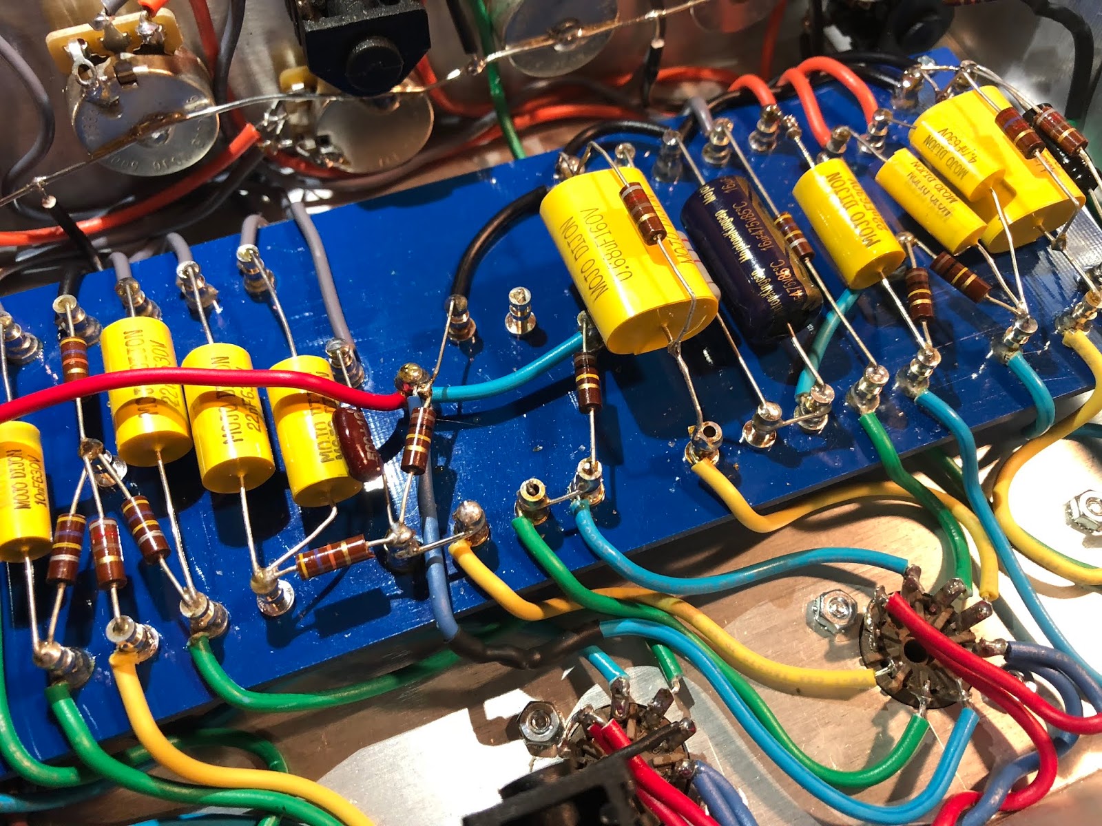
DANGER... That 100K resistor lead appears to be very close to that turret. The resistor lead is connected to ground. The turret is connected to B+. I would do whatever it takes to insure the resistor lead cannot touch that turret.
Fizz... That 47pF is supposed to help eliminate fizz and high freq oscillation. Change it to 100pF and see if that helps.
DANGER... That 100K resistor lead appears to be very close to that turret. The resistor lead is connected to ground. The turret is connected to B+. I would do whatever it takes to insure the resistor lead cannot touch that turret.
You do not have the required permissions to view the files attached to this post.
Re: HOW DOES THE MOJO 18 W TMD LAYOUT LOOK TO YOU? EXPERT OPINIONS NEEDED.
Thanks.
I thought you might see that 100K. I cut it from the neighboring turret and soldered an extension to reach the new turret. The angle of the photo makes it look like it's close. I'll double check that and try the 100 pF as well.
I thought you might see that 100K. I cut it from the neighboring turret and soldered an extension to reach the new turret. The angle of the photo makes it look like it's close. I'll double check that and try the 100 pF as well.
Just plug it in, man.
Re: HOW DOES THE MOJO 18 W TMD LAYOUT LOOK TO YOU? EXPERT OPINIONS NEEDED.
Referring to your pic... I would move the bottom lead of that 100K over to the turret with the yellow wire. That will probably give plenty of separation between the top lead and that B+ turret.