SDM SILVER JUBILEE

Marshall Amp Discussion

Moderators: pompeiisneaks, Colossal

User avatar
ViperDoc
Posts: 1247
Joined: Tue Dec 24, 2019 2:21 am
Location: Idaho

Re: SDM SILVER JUBILEE

Post by ViperDoc »

Here is the SCH for the 2550X with independent gain controls! (more what I had in mind anyway--50W)!!! Everything happens for a reason, baby. SWEET!!!

Image

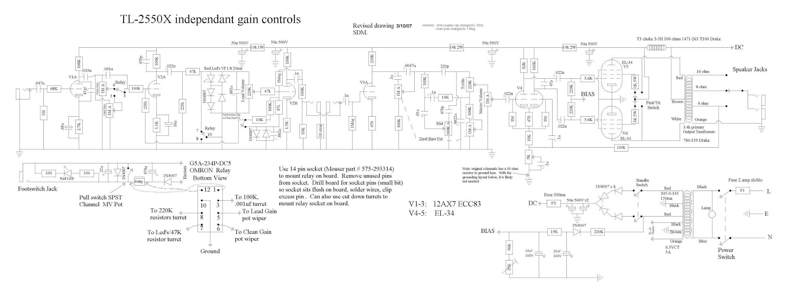
The LEDs are inside the lead circuit. (I know I cheated by looking at this first before posting it. 8) )The clipping diodes on the gain pot pull to engage the two 1n4007 diodes to ground further over on the board. I'm curious what the point of the LEDs are? Any other designs employ this? The SCH says the red LED is good for a 1.8 voltage drop, but I don't know how that would impact the tone.

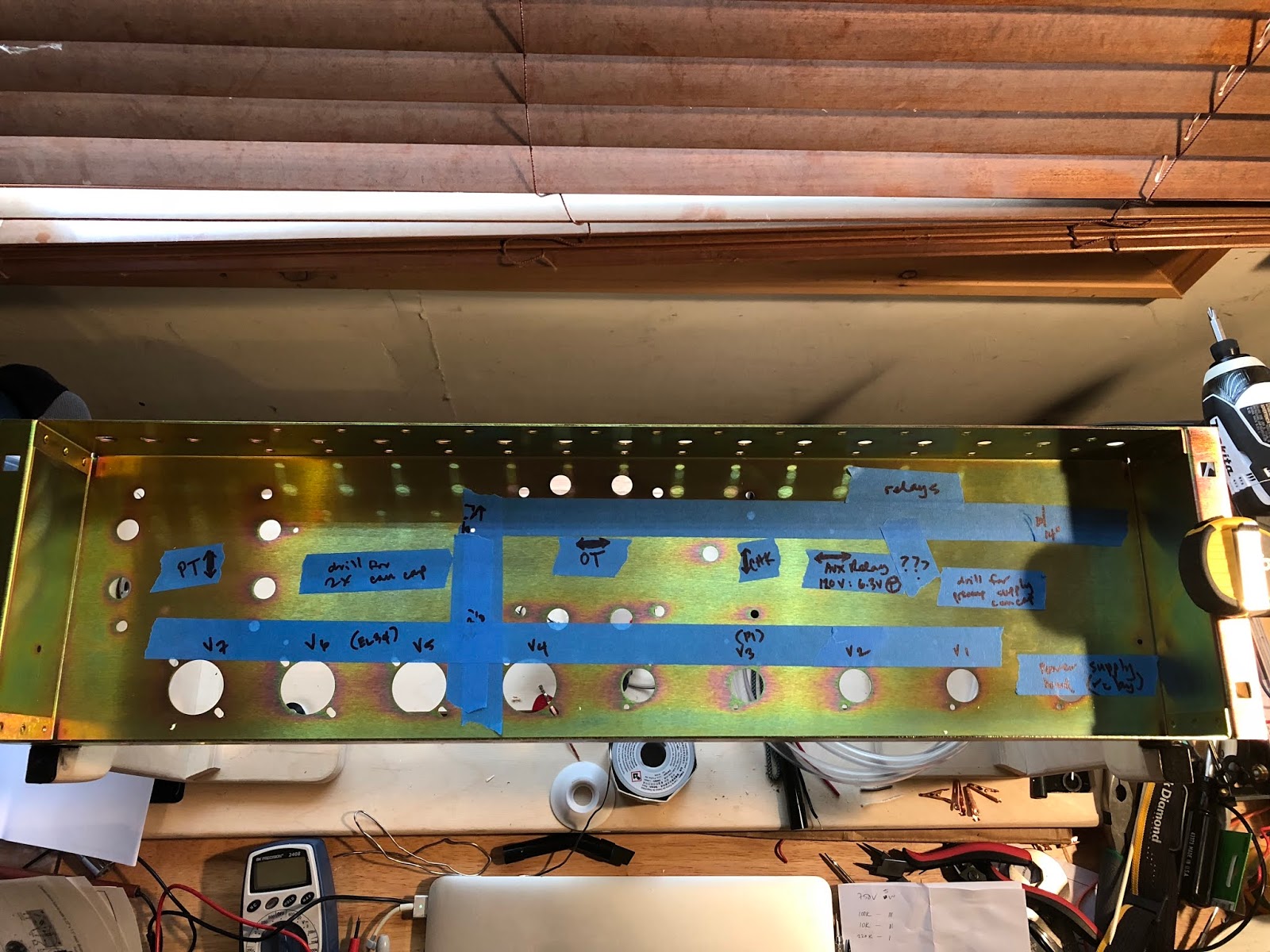
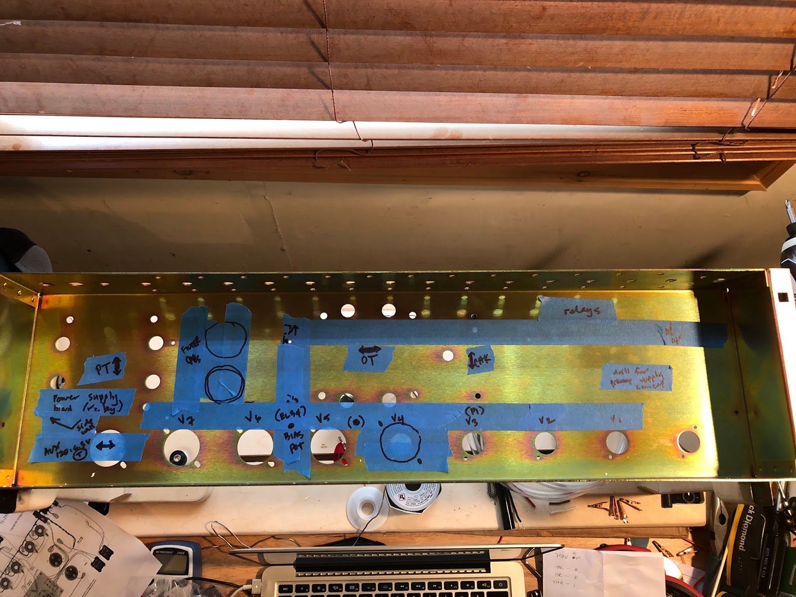
Here's the 50W layout, all thanks to SDM:

Image

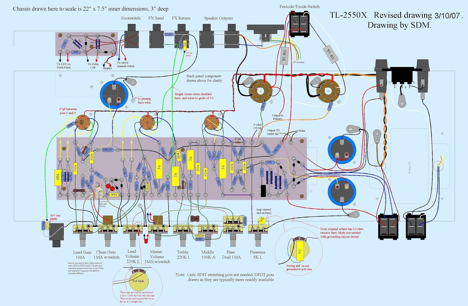
He also notes the relay power supply on this layout is outdated. I imagine i could just use the Hoffman power supply.
Just plug it in, man.
User avatar
ViperDoc
Posts: 1247
Joined: Tue Dec 24, 2019 2:21 am
Location: Idaho

SDM SILVER JUBILEE--EFFECTS LOOP DELETION?

Post by ViperDoc »

I've been looking at this SJ SCH and am interested in moving the effects loop. I don't want to color my loop with the preamp tone stack. How would you delete this loop? The R33, R36 and R57 specifically, are those part of the loop circuit?
I'm going to put in a Metro Zero Loss loop in between the tone stack and the MV.
TL 2550X schemR11.JPG
You do not have the required permissions to view the files attached to this post.
Just plug it in, man.
sluckey
Posts: 3079
Joined: Sun Jul 22, 2007 7:48 pm
Location: Mobile, AL
Contact:

Re: SDM SILVER JUBILEE--EFFECTS LOOP DELETION?

Post by sluckey »

ViperDoc wrote: Mon Feb 24, 2020 4:34 pm How would you delete this loop? The R33, R36 and R57 specifically, are those part of the loop circuit?
Those reference designators are not on that schematic. I'd try this...
You do not have the required permissions to view the files attached to this post.
User avatar
ViperDoc
Posts: 1247
Joined: Tue Dec 24, 2019 2:21 am
Location: Idaho

Re: SDM SILVER JUBILEE

Post by ViperDoc »

Thanks, Steve! You're right, I was recalling numbers from the Marshall SCH. See below:
Marshall_25aniv_silverjubilee_50_100w_2555.pdf
I'll give that a shot! The more I think about this amp, I'm going to do a 100W 2555"X" with the individual gains. With the Metro Loop, this thing is going to be a monster.

I've been looking into Drake vs. Dagnall wound OTs. Any recommendations? Seems like the Drake's were in the more original Marshalls and Dagnalls took over for the "newer models". Also preferred by Friedman.
You do not have the required permissions to view the files attached to this post.
Just plug it in, man.
User avatar
ViperDoc
Posts: 1247
Joined: Tue Dec 24, 2019 2:21 am
Location: Idaho

Re: SDM SILVER JUBILEE

Post by ViperDoc »

Here's a draft of a 2-discreet channel 2555X I just whipped up (it took hours) using KiCAD.

[ATTACHMENT REMOVED BECAUSE IT'S WRONG]

EDIT: NOTE--THIS IS A WORK IN PROGRESS. IT IS NOT A VALID OR COMPLETED SCHEMATIC. IT SUCKS. DO NOT TRUST IT.
Last edited by ViperDoc on Thu Feb 27, 2020 9:35 pm, edited 3 times in total.
Just plug it in, man.
sluckey
Posts: 3079
Joined: Sun Jul 22, 2007 7:48 pm
Location: Mobile, AL
Contact:

Re: SDM SILVER JUBILEE

Post by sluckey »

That's loaded with errors.
User avatar
ViperDoc
Posts: 1247
Joined: Tue Dec 24, 2019 2:21 am
Location: Idaho

Re: SDM SILVER JUBILEE

Post by ViperDoc »

Sluckey, I redrew that from the SDM schematic and noticed it looked slightly different from the Marshall, so I need to go over it again. Thanks for looking at it!

I see I forgot to update the gridstop(?) resistors to 220K. I copy pasted those but forgot to input the right value.

I need to learn how to control the node layouts in the power tube section on this software. That looks like a mess.
Just plug it in, man.
User avatar
ViperDoc
Posts: 1247
Joined: Tue Dec 24, 2019 2:21 am
Location: Idaho

OK, NO MORE DRAWINGS AT 2:00 AM!

Post by ViperDoc »

Here's a corrected schematic I based off of the Marshall 2555 SCH from drtube.com. It's still a work in progress, but looks quite a bit better. Your advice is much appreciated.
VIPERDOC 2555X SCH 1.2.pdf
You do not have the required permissions to view the files attached to this post.
Just plug it in, man.
User avatar
ViperDoc
Posts: 1247
Joined: Tue Dec 24, 2019 2:21 am
Location: Idaho

Re: SDM SILVER JUBILEE

Post by ViperDoc »

What is the right way to isolate tone controls per channel in a channel-switching Marshall-style amp? My previous SCH placed relays pre- and post-tone control, and when one tone stack is selected, the other appears to be in a ground loop of sorts. I decided to sketch a version where both tone stacks are connected off the V2B plate and then the relay dumps the unused tone stack to ground. What's the best way to design it?

Also, I sketched in how a 2-master volume setup might look, but the Lead master would likely be redundant given there are separate Lead channel gain and volume controls. My only thought was whether it might be cool to run lower lead gain before V2 and then have the option of boosting it post-tone stack. What would you do? Thanks.

[EDIT: REMOVED B/C it’s also wrong!]
Last edited by ViperDoc on Sun Apr 12, 2020 8:39 am, edited 1 time in total.
Just plug it in, man.
User avatar
dorrisant
Posts: 2628
Joined: Tue Sep 21, 2010 1:27 pm
Location: Somewhere between a river and a cornfield
Contact:

Re: SDM SILVER JUBILEE

Post by dorrisant »

Is there a repository of these schems and layouts?
"Education is what you're left with after you have forgotten what you have learned" - Enzo
User avatar
ViperDoc
Posts: 1247
Joined: Tue Dec 24, 2019 2:21 am
Location: Idaho

Re: SDM SILVER JUBILEE

Post by ViperDoc »

The most comprehensive Marshall SCH database I've seen is on www.drtube.com. Go here for a chronological list:

https://drtube.com/library/schematics/6 ... hemas#AN25
Just plug it in, man.
User avatar
ViperDoc
Posts: 1247
Joined: Tue Dec 24, 2019 2:21 am
Location: Idaho

Re: SDM SILVER JUBILEE

Post by ViperDoc »

I just noticed the SDM schematic lists the preamp triodes in the order of V1A, V2A, V2B, V3A, and then V4 as the PI. Is this amp designed to have 4 12AX7 tubes, two of which only use one side, or is this a mistake and it should be V1A-B, V2A-B, V3? Would there be any difference?

[EDIT: NEVER MIND. THE LAYOUT TELLS ALL. V1-3.]
Just plug it in, man.
User avatar
ViperDoc
Posts: 1247
Joined: Tue Dec 24, 2019 2:21 am
Location: Idaho

CHASSIS LAYOUT

Post by ViperDoc »

With all this down time, I thought I'd do some work on the chassis layout. My question is this:

Where is the best place to mount an auxillary 120V:6.3V CT transformer for powering the relay circuits? I know it's ideal to mount the trafos perpendicular in sequence, right? I thought it might be best to not send 120V across the chassis, better to send the 6.3V over an insulated wire...but where do I put it? I could put it above or below the filter caps (need to drill the holes), but it would be right in between the PT/OT. Or I could displace V4-7 to the right and put it where the leftmost octal socket hole is. OR, I could just stick it in the lower left corner. Any advice?

Image

Thanks.
Just plug it in, man.
User avatar
ViperDoc
Posts: 1247
Joined: Tue Dec 24, 2019 2:21 am
Location: Idaho

Re: SDM SILVER JUBILEE

Post by ViperDoc »

Here's an updated alternative rough-out:

Image
Just plug it in, man.
User avatar
martin manning
Posts: 13210
Joined: Sun Jul 06, 2008 12:43 am
Location: 39°06' N 84°30' W

Re: SDM SILVER JUBILEE

Post by martin manning »

Anything going on the left sidewall? Looks like there's room for the transformer and the power supply board there.
Post Reply