Silver Jube Clone Oscillation?

Marshall Amp Discussion

Moderators: pompeiisneaks, Colossal

User avatar
ViperDoc
Posts: 1247
Joined: Tue Dec 24, 2019 2:21 am
Location: Idaho

Silver Jube Clone Oscillation?

Post by ViperDoc »

Welcome to the next episode!

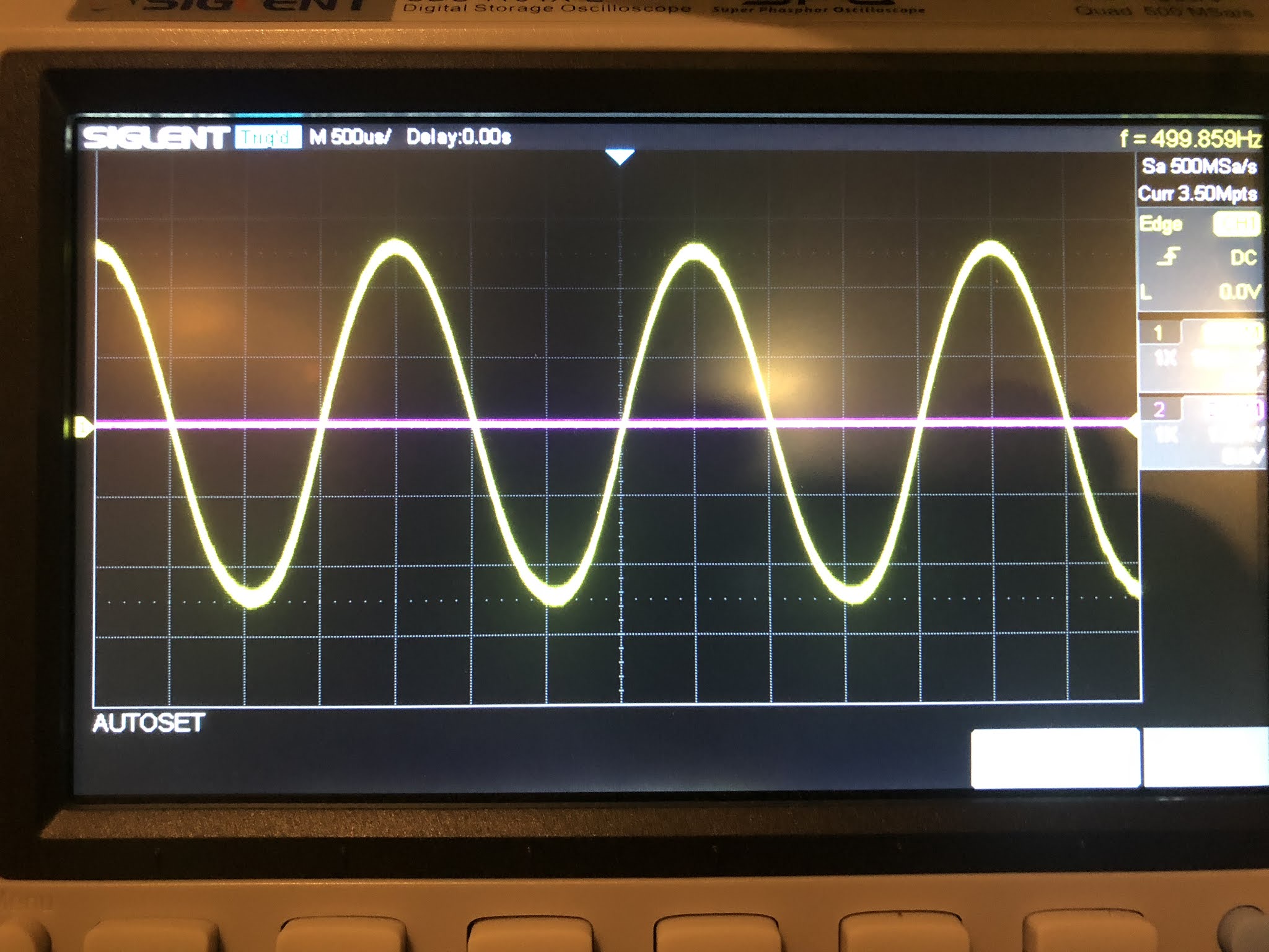
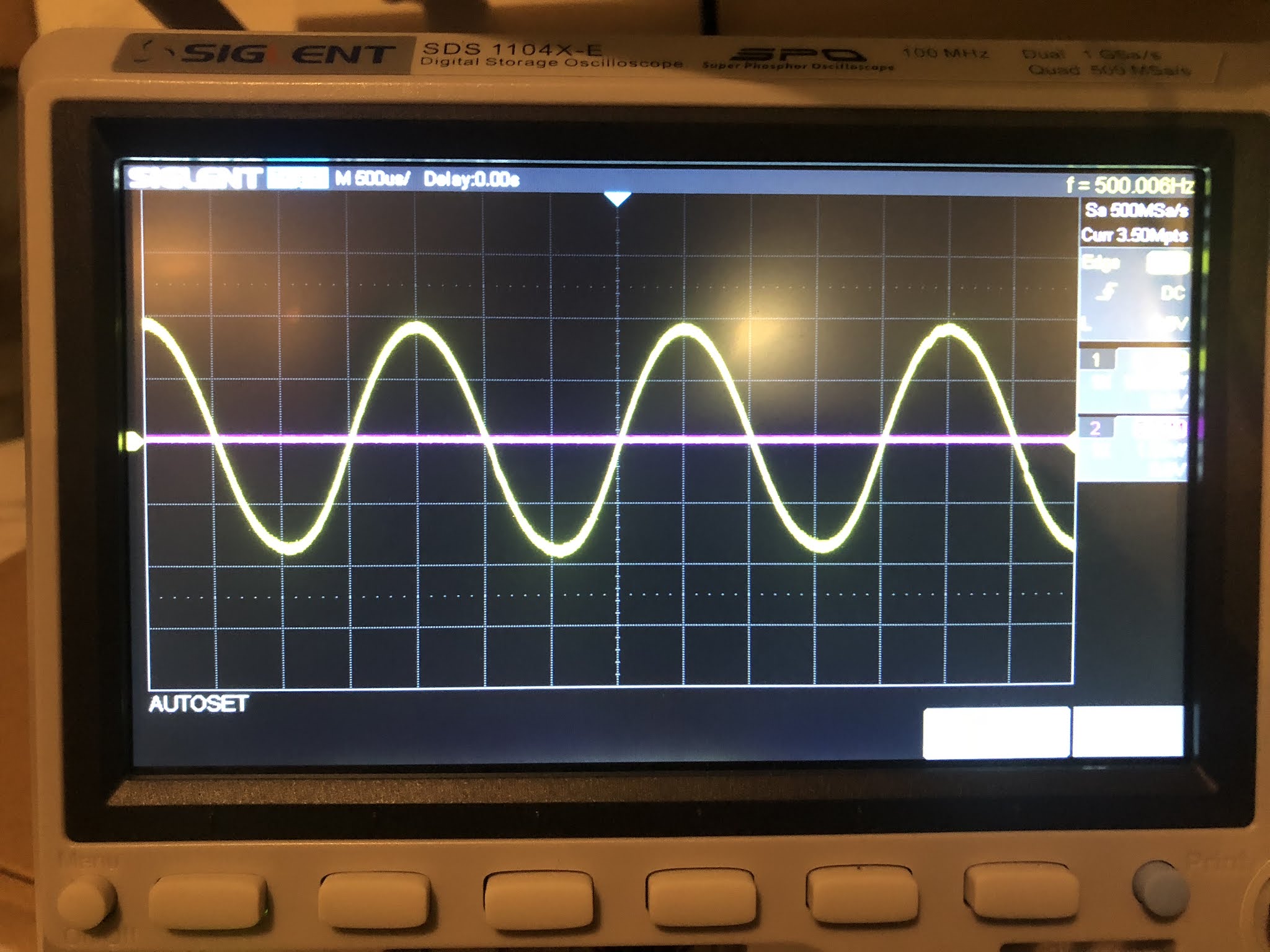
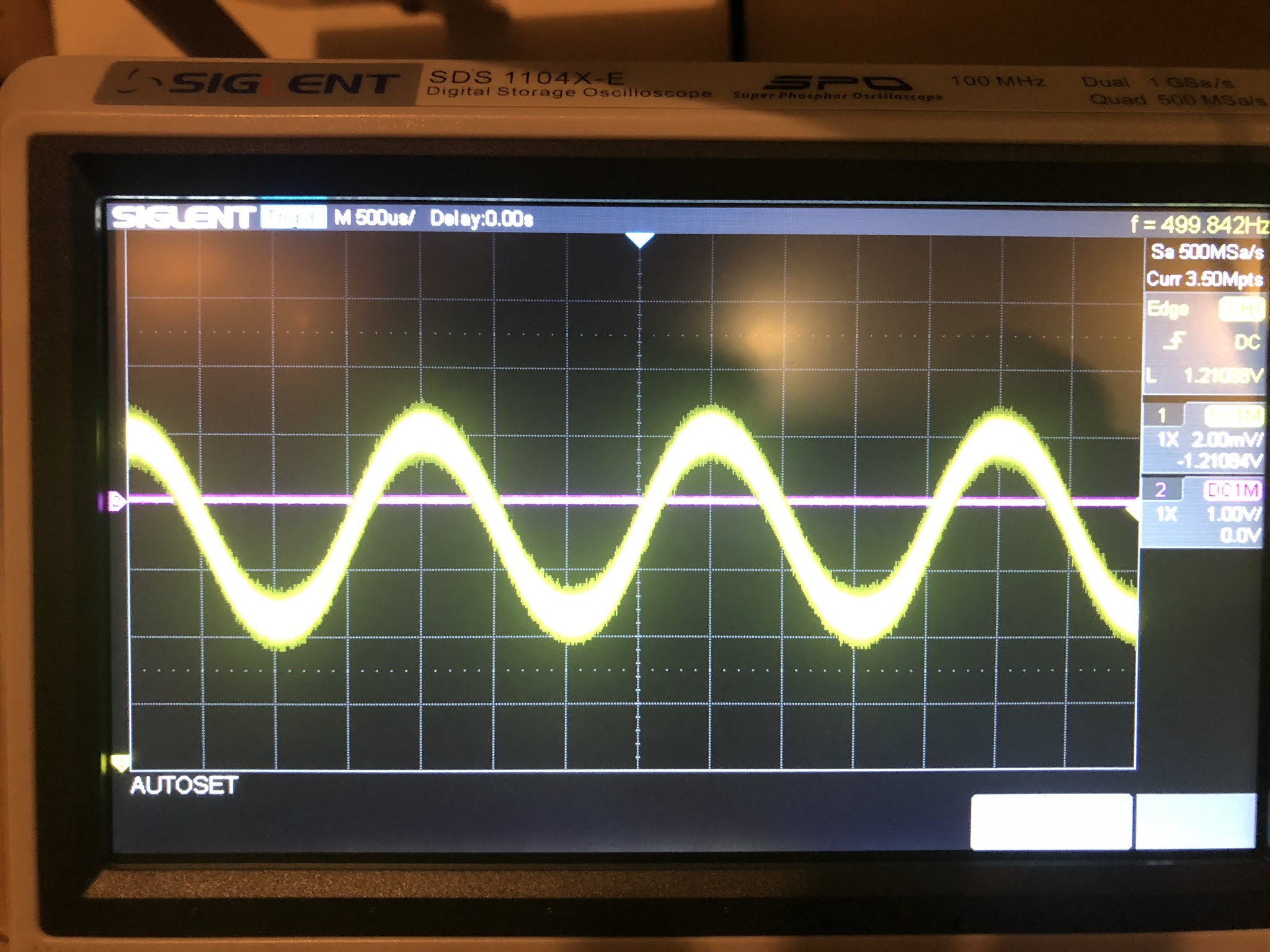
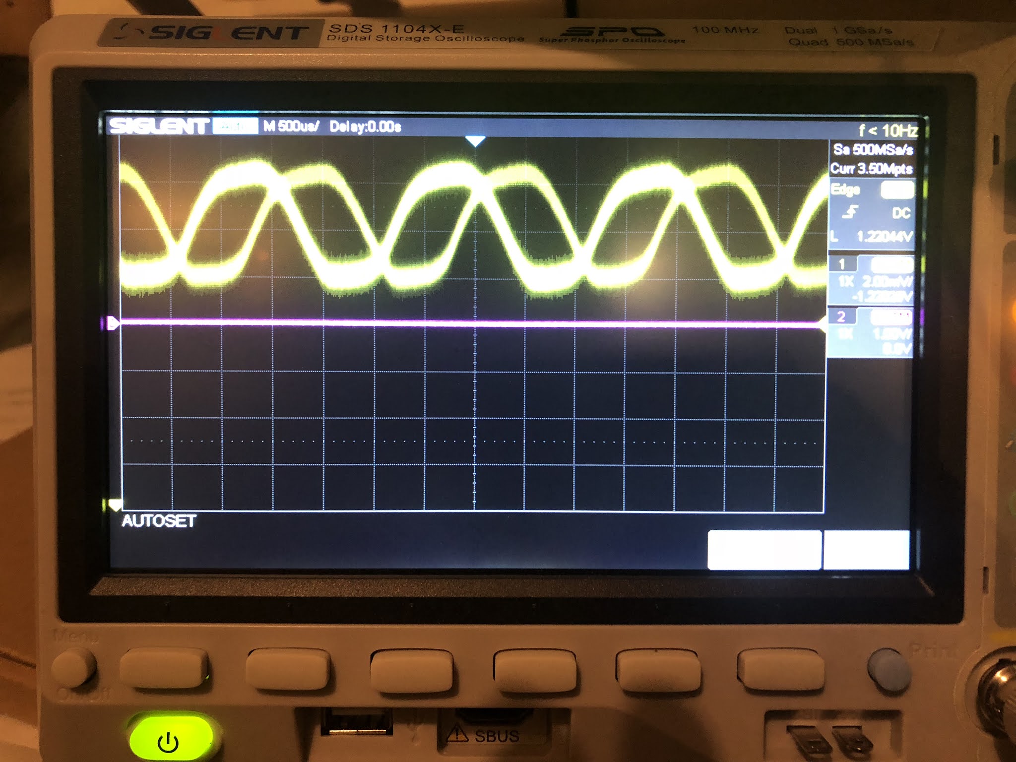
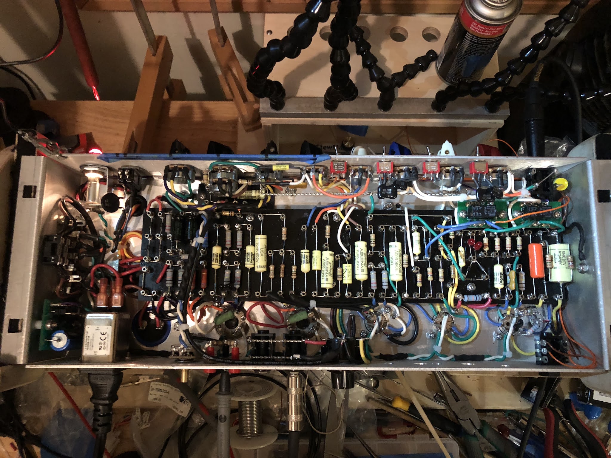
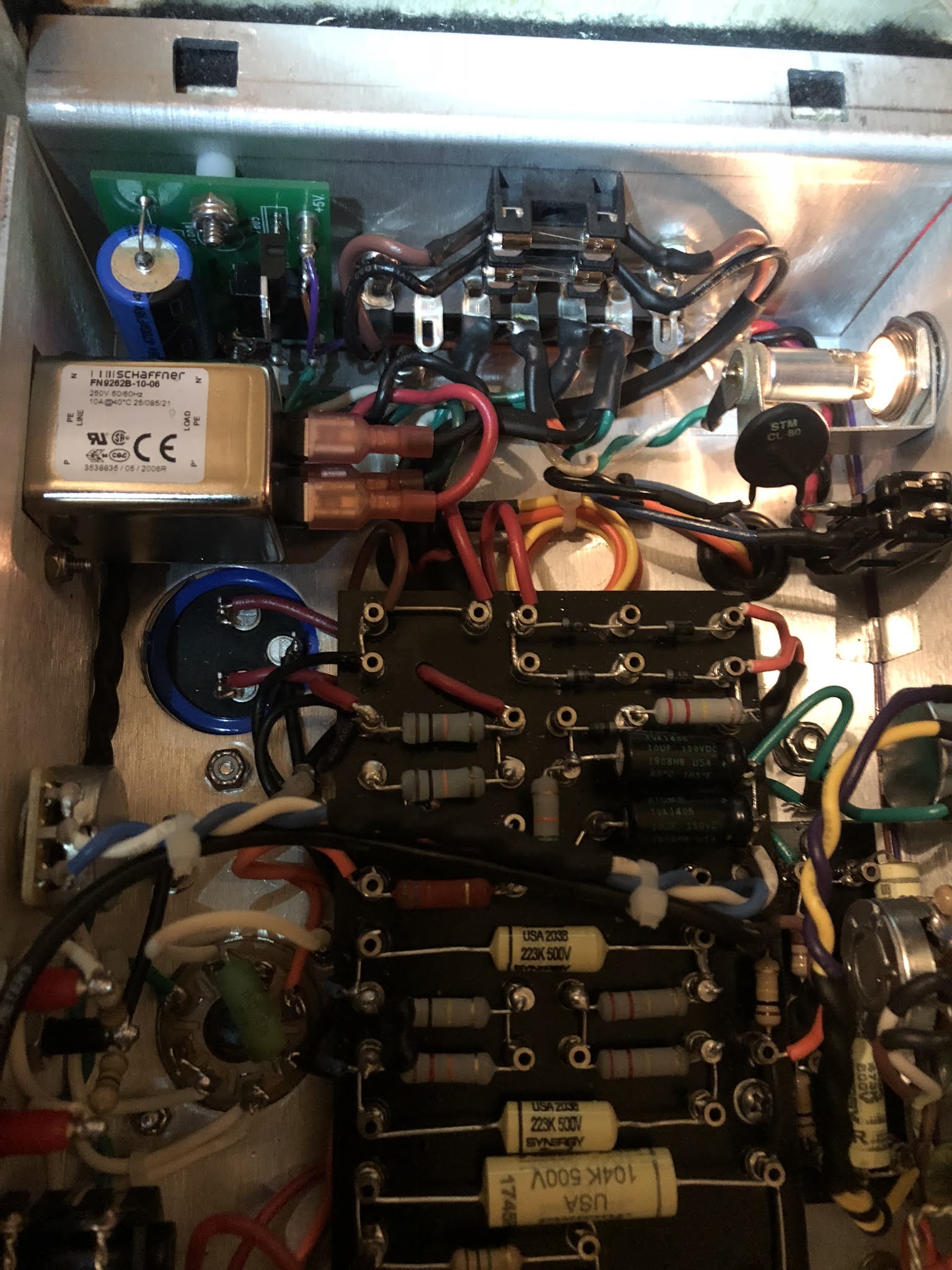
I just fired up my newly built 2550X Silver Jubilee based on the SDM files from Valvestorm with only a few modifications as usual, and shoehorned into an 18-watt chassis. Data below. The amp is fully functional at the slightest opening of the master volume. When not playing, it's whisper quiet. No red-plating. The preamp controls all function, the relays and switches all function. When I turn up the master, it starts to sound like a bitcrusher when playing notes. I reversed the OT primary leads and got the same thing except it sounded like a nuclear fuzz pedal at all settings. Just initially thinking this through with my limited knowledge, I could be getting oscillation with the presonance part of the circuit as others have reported, or the FX loop delete point. Not sure. Here's the data and photos:

2550X SILVER JUBILEE CLONE A LA SDM

PT: HEYBOER 50W APD-8023H
OT: HEYBOER 50W APD-8025H
CHOKE: HAMMOND 159R 200mA 150R 500V
Electro Harmonix EL34, 12AX7s
F&T 50uF can capacitors
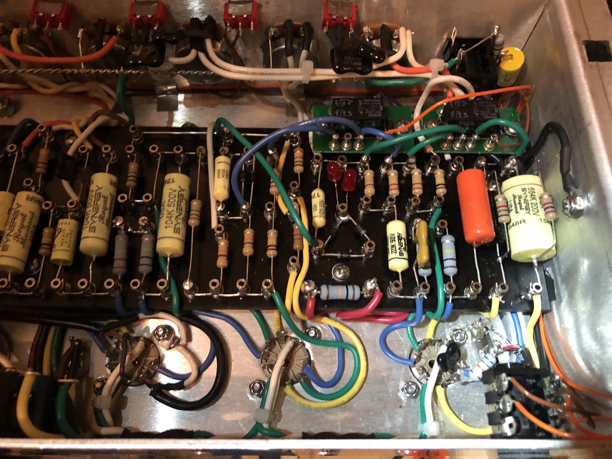
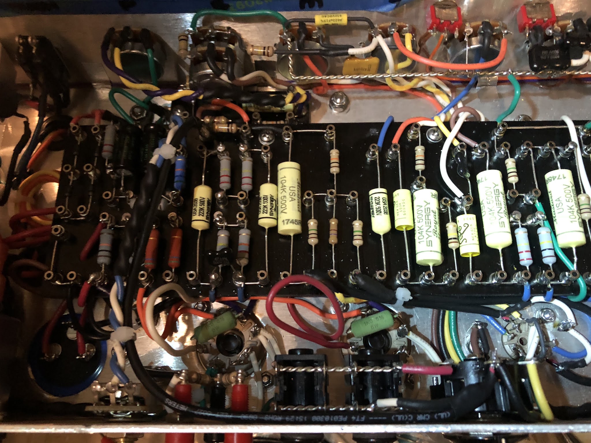
Synergy Mustard/Sozo caps
Sprague Atom E-lytics

Mods:
1) Schaffner AC Module
2) Standby switch delete--CL80 Thermistor on AC Hot post-switch
3) 500 mA fuses on HT and 6.3V heater CTs
4) Individual Lead and Clean Gain controls
5) Clean and Lead 3-way Bright switches
6) Hoffman 5VDC relay boards and power supply
7) Custom board
8) Manning Presonance Mod
9) Original FX Loop delete (Metro ZL Loop to be installed later)
10) Default Clean channel instead of Lead.
11) Direct Out delete
12) Half-Power switch delete

Image

Image

Image

Image

VOLTAGES:

WALL AC = 120V
HTS = 333 VAC
B+ = 427 VDC
HEATERS = 6.3 VAC

V1:
P1 = 236
P3 = 1.8
P6 = 209
P8 = 1.4

V2:
P1 = 210
P3 = 1.6
P6 = 107
P8 = 0.47

V3:
P1 = 239 [corrected]
P2 = 24.9
P3 = 40
P6 = 233
P7 = 26.2
P8 = 40

V4:
P3 = 425
P4 = 421
P5 = -39.5
P8 = 34 mV

V5:
P3 = 426
P4 = 420
P5 = -39.5
P8 = 35 mV

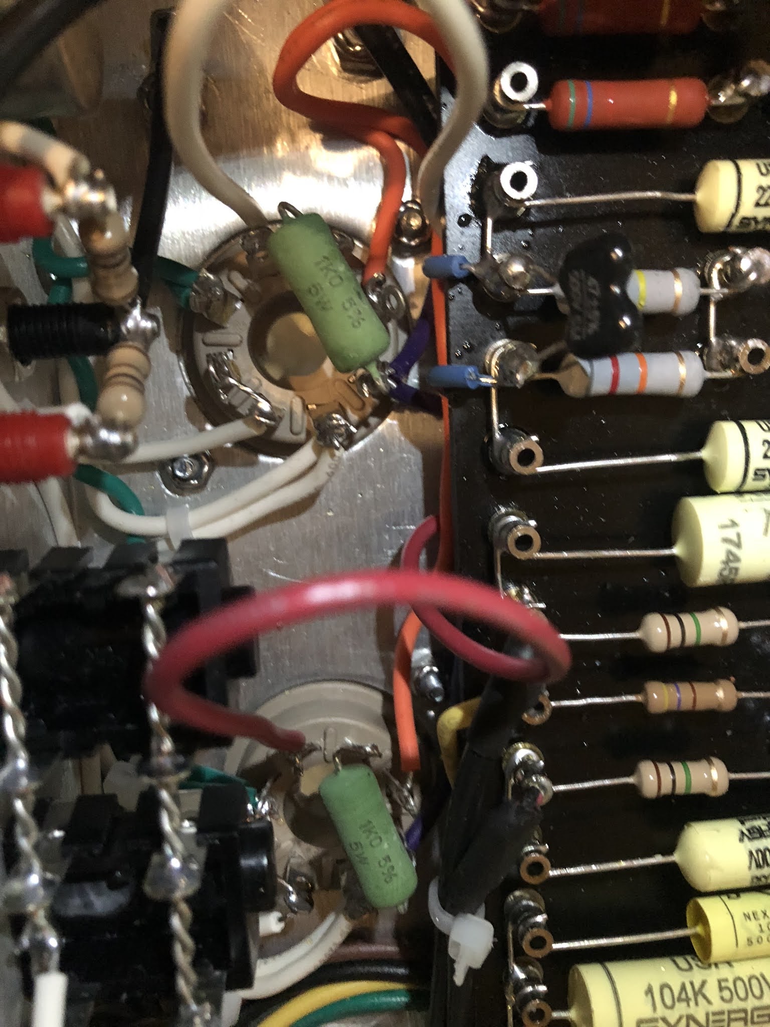
The Presonance circuit is on a small secondary board bolted underneath the bass control on the chassis with a G10 spacer underneath to prevent grounds. It was really hard to make room for everything on this build. I'm sure I could have done it better, but this is my first Jube, so I appreciate your advice. I thought I'd ask before I replace the Presonance with a 5K/0.1uF presence control like the SDM "original". Thanks as always!

[nfb tap corrected from 8R to 4R]
[PI PLATE LOAD RESISTORS ADDED!]
VIPERDOC 2550X BUILD 1.2 SCH.pdf
Original SDM 2550X SCH:
TL 2550X schemR11.JPG
Original SDM Layout:
https://el34world.com/Forum/index.php?a ... 0023;image
You do not have the required permissions to view the files attached to this post.
Last edited by ViperDoc on Fri Aug 06, 2021 9:43 pm, edited 7 times in total.
Just plug it in, man.
User avatar
ViperDoc
Posts: 1247
Joined: Tue Dec 24, 2019 2:21 am
Location: Idaho

Re: Silver Jube Clone Oscillation?

Post by ViperDoc »

Some scope shots. I've never learned the correct way to trace a circuit, but perhaps these photos may help. I sent a 1V 500 Hz signal to the input jack with a generator.

Here's the common OT output:

Image

4 ohm OT tap NFB lead before the 100K NFB resistor:

Image

Just on the other side of the 100K NFB resistor (where my presonance circuit joins in):

Image

The signal is incredibly noisy here, yes? When do you suspect a bad resistor vs. a bad presonance circuit, for example?

With a hotter signal previously at the post 100K NFB resistor. The signal wouldn't sit still:

Image

I took a look through the preamp and the waveform takes various shapes depending on the settings, but looks clean. What else would be helpful? Thank you.
Just plug it in, man.
User avatar
xtian
Posts: 7015
Joined: Mon Apr 19, 2010 8:15 pm
Location: NorCal
Contact:

Re: Silver Jube Clone Oscillation?

Post by xtian »

Lovely work, there, doc! Start by disconnecting NFB. Does the amp play OK?
I build and repair tube amps. http://amps.monkeymatic.com
sluckey
Posts: 3086
Joined: Sun Jul 22, 2007 7:48 pm
Location: Mobile, AL
Contact:

Re: Silver Jube Clone Oscillation?

Post by sluckey »

Just a tip on using your scope. There is a USB port and a print button under the display. Simply insert a thumb drive and press print. The entire screen will be captured and saved as an image file on the thumb drive. Much easier and better resolution than taking a picture of your scope. Might look something like this...
You do not have the required permissions to view the files attached to this post.
User avatar
ViperDoc
Posts: 1247
Joined: Tue Dec 24, 2019 2:21 am
Location: Idaho

Re: Silver Jube Clone Oscillation?

Post by ViperDoc »

I appreciate the hot tips, Sluckey & xtian!

As always, it's good to have popcorn on hand. I disconnected the NFB wire from the 100K resistor and lit up the amp. The Master started to take more volume and I could see that the controls all work, although the distortion sounds horrendous, less but still like a bitcrusher, with much less output than expected. Then there was a white flash and no sound anymore! YAY! I blew the HT fuse. Tubes still look fine. Should have used the bulb limiter. :oops:

I'm headed to a family reunion tomorrow for a week, so I won't be able to do much until I return.

Just to be clear, when I played the circuit with the master only cracked open to hear sound out of the cab, it sounds like rock and roll! Clean to crunch on the clean channel, dirty and mean on the lead channel. Pinch harmonic bliss. Good EQ. Looking forward to cracking the code.
Just plug it in, man.
User avatar
xtian
Posts: 7015
Joined: Mon Apr 19, 2010 8:15 pm
Location: NorCal
Contact:

Re: Silver Jube Clone Oscillation?

Post by xtian »

"Bitcrusher" sounds like gated fuzz, right? That's often caused by lack of grid-to-ground reference--each stage's control grid must be referenced to ground via a resistive path. But you burned something up, so there's obviously more than one issue here. Very curious. Looking forward to solving this.
I build and repair tube amps. http://amps.monkeymatic.com
User avatar
ViperDoc
Posts: 1247
Joined: Tue Dec 24, 2019 2:21 am
Location: Idaho

Re: Silver Jube Clone Oscillation?

Post by ViperDoc »

xtian wrote: Sat Jul 31, 2021 5:25 pm "Bitcrusher" sounds like gated fuzz, right? That's often caused by lack of grid-to-ground reference--each stage's control grid must be referenced to ground via a resistive path. But you burned something up, so there's obviously more than one issue here. Very curious. Looking forward to solving this.
Right, it was worse in the beginning when turning up the master, then less so when I disconnected the NFB feed until I blew the fuse. I'll double-check my grid connections, thanks for that.
Just plug it in, man.
User avatar
ViperDoc
Posts: 1247
Joined: Tue Dec 24, 2019 2:21 am
Location: Idaho

Re: Silver Jube Clone Oscillation?

Post by ViperDoc »

Corrections made to update the schematic to the build.
Last edited by ViperDoc on Sun Aug 01, 2021 4:20 am, edited 2 times in total.
Just plug it in, man.
User avatar
ViperDoc
Posts: 1247
Joined: Tue Dec 24, 2019 2:21 am
Location: Idaho

Re: Silver Jube Clone Oscillation?

Post by ViperDoc »

Another thought was how I removed the stock effects loop. If I removed only the jacks (and run the circuit as a stock amp without the stock loop in use), it would look like this:
VIPERDOC 2550X FX JACKS REMOVED.pdf
[EDIT: I decided to splice in the 100K:10K to ground with the additional 0.1 uF cap going into the V2B grid, NFB still disconnected. With the bulb limiter and power tubes in, the amp will turn on and warm up for about 10-15 seconds, then short.

I also pulled the power tubes and found no shorts on either, just heater continuity.]
You do not have the required permissions to view the files attached to this post.
Just plug it in, man.
User avatar
xtian
Posts: 7015
Joined: Mon Apr 19, 2010 8:15 pm
Location: NorCal
Contact:

Re: Silver Jube Clone Oscillation?

Post by xtian »

ViperDoc wrote: Sat Jul 31, 2021 6:40 pmI decided to splice in the 100K:10K to ground with the additional 0.1 uF cap going into the V2B grid, NFB still disconnected. With the bulb limiter and power tubes in, the amp will turn on and warm up for about 10-15 seconds, then short.
I also pulled the power tubes and found no shorts on either, just heater continuity.]
I'm confused. You "decided" to throw in a voltage divider that dumps 90% of your signal to ground? And there's a mysterious path entering from the left and connecting to the right side of that first 0.1u cap. WHT?

With a new build, one would normally power up for the first time with NO tubes installed, and take a voltage survey, making sure everything was stable, and that your -ve bias supply was good. Did you do this?
I build and repair tube amps. http://amps.monkeymatic.com
User avatar
xtian
Posts: 7015
Joined: Mon Apr 19, 2010 8:15 pm
Location: NorCal
Contact:

Re: Silver Jube Clone Oscillation?

Post by xtian »

Your photos are too small and dark for me to see where the power tube's index pin is, so I can't tell if the power tube sockets are wired correctly.
I build and repair tube amps. http://amps.monkeymatic.com
User avatar
ViperDoc
Posts: 1247
Joined: Tue Dec 24, 2019 2:21 am
Location: Idaho

Re: Silver Jube Clone Oscillation?

Post by ViperDoc »

xtian wrote: Sat Jul 31, 2021 10:48 pm
ViperDoc wrote: Sat Jul 31, 2021 6:40 pmI decided to splice in the 100K:10K to ground with the additional 0.1 uF cap going into the V2B grid, NFB still disconnected. With the bulb limiter and power tubes in, the amp will turn on and warm up for about 10-15 seconds, then short.
I also pulled the power tubes and found no shorts on either, just heater continuity.]
I'm confused. You "decided" to throw in a voltage divider that dumps 90% of your signal to ground? And there's a mysterious path entering from the left and connecting to the right side of that first 0.1u cap. WHT?

With a new build, one would normally power up for the first time with NO tubes installed, and take a voltage survey, making sure everything was stable, and that your -ve bias supply was good. Did you do this?
Let me try to explain. The Marshall 2550 has a stock FX loop in between V2A and V2B before the EQ and MV. One goal with this build was to remove that stock loop and place a Metro ZL loop between the treble output and MV as per current "norms". I received a kind recommendation to remove the components and modify the 2550 circuit as shown in my original build schematic. The stock loop has a 100K, 10K and 0.1 uF cap that were deleted in the advice I got, so that's how I originally built it. My reason for replacing the 100K, 10K and 0.1uF caps was to restore that part of the circuit to "what it would be" with the original loop in place but with no cables inserted (not in use). That's the only reason. Does that make sense?

Here's the Marshall 2550 SCH:
Marshall_25aniv_silverjubilee_25_50w_2550.pdf
NOTE: I just noticed something I've never caught before. This may be of no consequence, but the 47 pF "fizz" cap that I'm used to seeing between PI plate load resistors is drawn on the above Marshall 2550 SCH *AFTER* the PI .022 uF filter caps, between the 220K PT grid leak resistors. No connection to my problem, I'd think, but I wonder what difference that would make?

I first fired this chassis up on the limiter without tubes to check bias voltage and it looked great. Once I put the tubes in, I was able to adjust to 38 mA on both PT cathodes, my EL34 pair being only slightly unmatched (I think I averaged 37 mA). See the original voltages I posted. I could play the amp just fine so long as the MV was only a hair open, and then it started puking as I turned it up.

Referring to the Ceriatone voltage chart for their clone of this amp, my startup voltages look to be in the ballpark.

Here's the Ceriatone 2550 layout:
Ceriatone 2550-Layout-010718.jpeg
You do not have the required permissions to view the files attached to this post.
Last edited by ViperDoc on Sun Aug 01, 2021 2:05 am, edited 5 times in total.
Just plug it in, man.
User avatar
ViperDoc
Posts: 1247
Joined: Tue Dec 24, 2019 2:21 am
Location: Idaho

Re: Silver Jube Clone Oscillation?

Post by ViperDoc »

xtian wrote: Sat Jul 31, 2021 10:49 pm Your photos are too small and dark for me to see where the power tube's index pin is, so I can't tell if the power tube sockets are wired correctly.
It's tight in there! Here's a shot.

Image

pin 1-8 = wired to bias checkpoint:1R1W to ground.
pins 2, 7 = heater
pin 3 = plate to OT primary
pin 4 = screen grid to 1K 5W resistor to pin 6
pin 5 = to individual 5K6 gridstoppers
pin 6 = wired to B+2 node post choke

Here's a layout to make sense of that mess:
VIPERDOC 2550X LAYOUT 1.0.pdf
Thanks as always.
You do not have the required permissions to view the files attached to this post.
Just plug it in, man.
User avatar
ViperDoc
Posts: 1247
Joined: Tue Dec 24, 2019 2:21 am
Location: Idaho

Re: Silver Jube Clone Oscillation?

Post by ViperDoc »

Are C19, C20 and R28 connected on the Marshall schematic? Or do C19 and C20 cross over the plate load resistor R28 with no connection? It only made sense to me that they all connected at the same node; otherwise, the only signal progressing through looks like the pre-grid signal, nullifying that gain stage.
Last edited by ViperDoc on Thu Aug 05, 2021 10:46 pm, edited 1 time in total.
Just plug it in, man.
User avatar
martin manning
Posts: 13239
Joined: Sun Jul 06, 2008 12:43 am
Location: 39°06' N 84°30' W

Re: Silver Jube Clone Oscillation?

Post by martin manning »

Yes, the 470p bypasses the plate load and the signal is taken out through the 22n. The C-tone layout shows the same.
Post Reply