martin manning wrote: ↑Sat Jan 13, 2024 9:45 pm
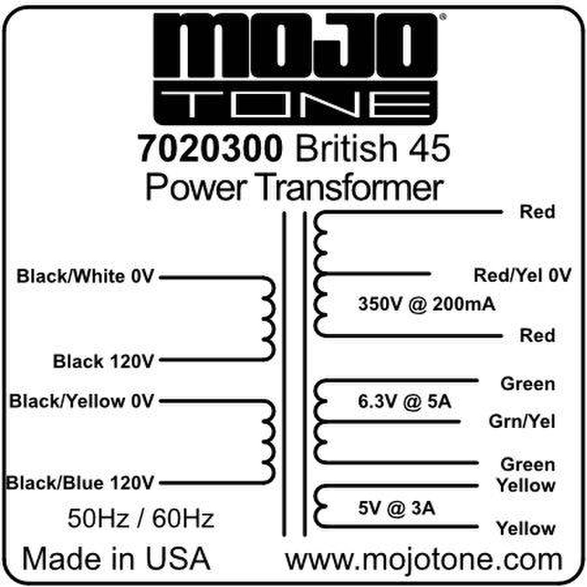
It doesn't seem like that PT was ever capable of 350-0-350 at 200 mA.
cdemike wrote: ↑Thu Oct 26, 2023 6:40 pm
There's not a lot of headroom, and while I was playing it after resetting the bias it made a crackling sound after I started testing the filter cap switch. It's now really low on gain (clean and quiet all the way up, whereas it had more gain than I wanted on 4/10 before the incident).
Do you still have that problem?
Unfortunately, after rethinking the measurements at the standby switch, I think you're right about the PT. Good to know moving forward, and hopefully someone else can avoid a similar issue in the future after reading this.
Regarding the low volume issue, I reflowed all of the joints on the board per xtian's advice during that initial round of revisions, and the issue went away. So it seems like it may have been a cold joint somewhere. Glad I posted about it before I brought the amp out for a gig, jam, rehearsal, etc. I also wanted to see if the noise issue would be fixed if I installed shields on the preamp tubes, which did fix that issue. Specifically a shield on V1 made all the noise go away, and now it's quiet as a mouse. I live in apartment, and our living room is where we both keep the music stuff and where the Wifi router lives, so I suspect the router was the main noise culprit.
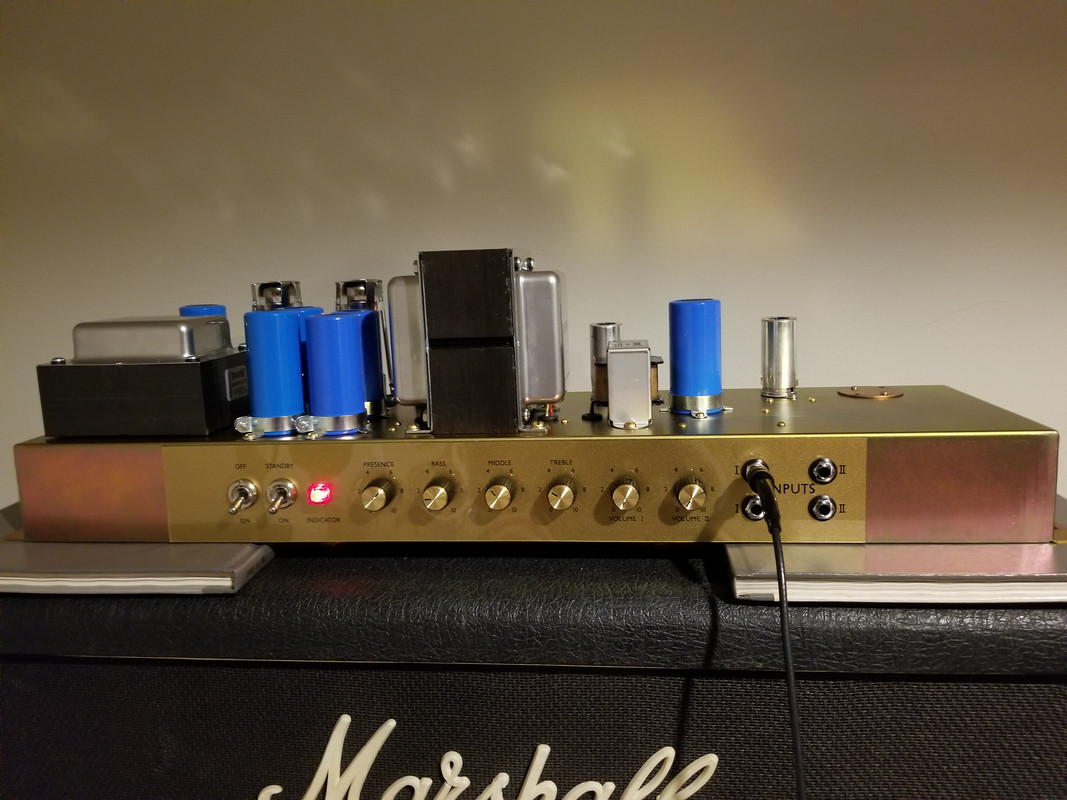
The headroom issue does remain, though. It produces more drive than most non-master Marshalls I've tried or owned. My concern is less that there's more overall drive available and more that I wish it would be more responsive to guitar volume and picking dynamic changes. Following the advice from the other thread, I set the B+ pretty high, and am currently getting about 380V at the PI node and 200V at the plate of V1. I measured the others while checking loaded vs unloaded B+ the other day but didn't write them down. If they're useful I'm happy to pass them on, but I do remember getting 185V at the cathode of the cathode follower, and I know 12AX7s are rated for a 200V maximum between the heaters and cathode. So while there probably is still some wiggle room in terms of preamp voltage, I'm thinking that's as close to maximum as I'd want to get if I ever gigged the amp and was unsure of wall voltages. I did buy some spare resistors to further lower resistance along the B+ rail in case I wanted to go down that road, but I'm hoping to get input about best ways to proceed in case someone else has a better solution.
I suspect that the low headroom may have something to do with the fact that the second gain stage is permanently bypassed. Given that I'm not huge on the 1.5uf cathode bypass cap in parallel with the always-on 0.68uf there, I may rework that to take the 0.68uf in and out of the circuit. I'd probably also change the cathode resistor to 1.5k to get more headroom from the stage, but I'm not completely convinced that's the source of the problem, given the big improvement in touch responsiveness after putting the 12BZ7 in the phase inverter. So I suspect I may be working the phase inverter and potentially the cathode follower too hard.
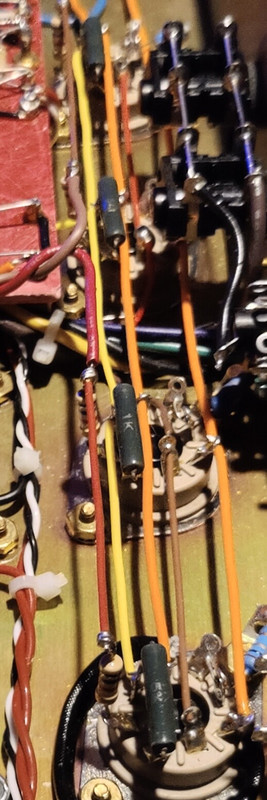
Filtering may also be a place I could focus. There is unsurprisingly a major improvement with the screens filters set higher, so I am also considering swapping the current 16/16uf can there for a 32/32uf can. My main hesitation is that I really like how saggy and vocal the amp is with 16uf on the screens. Currently this is how the B+ rail is set up: OT CT (switchable 50/100uf) > Choke > Screens (switchable 16/32uf) > 10k > PI (32uf) > 10k > V2 (16uf) > 10k > V1 (16uf)
So I also considered changing the preamp to 32uf on V1 and V2 64uf, but I'm not sure which node might be most effect -- maybe the PI? My main hesitation is that I really like the amp overall now except for the slight deficit in touch responsiveness, so I don't want to change too much around. I'm pretty embarrassed to admit that I'm pretty proud of how neat the amp's guts look (admittedly, a pretty distant second in priorities to how it sounds), so I don't want to end up with catawampus component leads.
