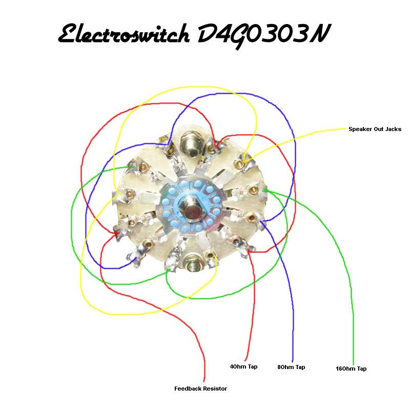
I'm pretty sure this is how to wire the Electroswitch DG40303N
[IMG:800:799]http://i205.photobucket.com/albums/bb17 ... Wiring.jpg[/img]
Anyone see anything weird?
Electroswitch Wiring Diagram
Moderators: pompeiisneaks, Colossal
-
UltraHookedOnPhonix

- Posts: 414
- Joined: Thu Dec 15, 2005 9:32 pm
- Location: Dumbleland
Re: Electroswitch Wiring Diagram
Whoa! 
Is this a joke?
If not, I just use the switch from Hoffman and connect four wires to it and call it a day.....
Is this a joke?
If not, I just use the switch from Hoffman and connect four wires to it and call it a day.....
Tom
Don't let that smoke out!
Don't let that smoke out!
-
UltraHookedOnPhonix
- Posts: 414
- Joined: Thu Dec 15, 2005 9:32 pm
- Location: Dumbleland
Re: Electroswitch Wiring Diagram
Actually, no.
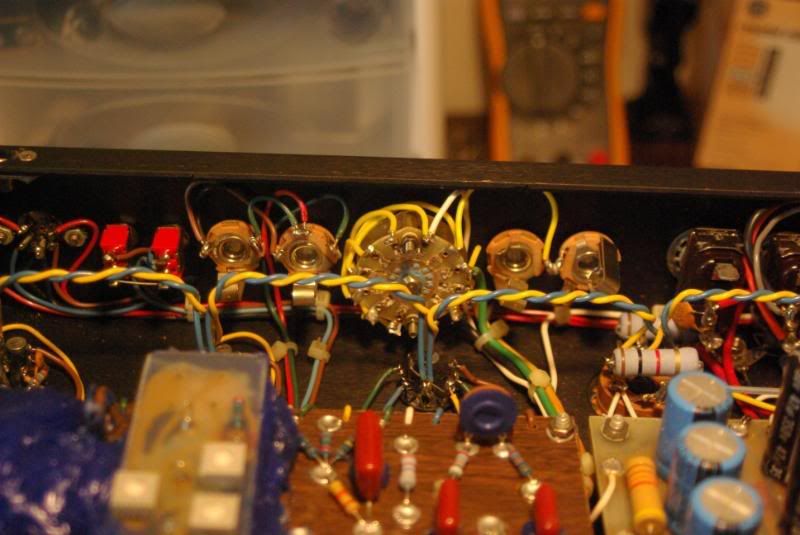
This is the exact switch used in many recent Dumble amps, like this one:
[IMG:800:535]http://i205.photobucket.com/albums/bb17 ... lector.jpg[/img]
If a connection goes bad on the switch you are talking about, your output transformer is left hanging without a load (ouch!!!). Not so with the wiring accomplished with this switch.
-
Guitarman18
- Posts: 453
- Joined: Tue Sep 04, 2007 9:32 pm
- Location: UK
Re: Electroswitch Wiring Diagram
Thanks for doing this UltraHookedOnPhonix. Even though I wired mine up a while back, (I haven't got trannies in, so have not test fired yet) it's nice to get confirmation that my grey cells are working.
-
martin manning

- Posts: 14058
- Joined: Sun Jul 06, 2008 12:43 am
- Location: 39°06' N 84°30' W
Re: Electroswitch Wiring Diagram
This is a 3-pole switch, so wired this way it is triple-redundant, and if all three contacts are functioning the current rating (per the data sheet) is 1.5A for each contact x 3 = 4.5A @ 28VDC. Even this is cutting it close though, since 100W into 4 Ohms is 5A (at 20V).
This seems to be a common theme from a fail-safe point of view, as you can see in the #124 pictures the PAB and OD DPDT slide switches are wired as two SPDT's in parallel.
MPM
This seems to be a common theme from a fail-safe point of view, as you can see in the #124 pictures the PAB and OD DPDT slide switches are wired as two SPDT's in parallel.
MPM
-
Noel Grassy

- Posts: 426
- Joined: Thu Feb 09, 2006 5:29 am
- Location: Vacuum Tube Valley-Cali
Re: Electroswitch Wiring Diagram
Yeah, but thankfully the Hoffman (NKK) switch has massive blades for each section. They'll glow for awhile before buckling and taking out your OT iron.
I like the triple redundancy factor never the less!
I like the triple redundancy factor never the less!
All excellent things are as difficult as they are rare__B Spinoza
-
tubedogsmith
- Posts: 597
- Joined: Mon Jan 17, 2005 11:52 pm
Re: Electroswitch Wiring Diagram
where do you get these things?
Re: Electroswitch Wiring Diagram
Excellent, thanks for posting I have been wondering about it for my HRM layout. Maybe there is some way I can show this on the HRM schematic.
Without the switch in hand, I was unable to figure that switch out based on the switches datasheet.
Without the switch in hand, I was unable to figure that switch out based on the switches datasheet.
-
Funkalicousgroove

- Posts: 2235
- Joined: Mon Jul 25, 2005 8:04 pm
- Location: Denver, CO
- Contact:
-
UltraHookedOnPhonix
- Posts: 414
- Joined: Thu Dec 15, 2005 9:32 pm
- Location: Dumbleland
Re: Electroswitch Wiring Diagram
-Tubedogsmith-
Seems the majority of these suppliers are running low on stock:
www.mouser.com Part#: 690-D4G0303N
www.alliedelec.com Part#: 747-7080
www.digikey.com Part#: 451-1099-ND
www.newark.com Part#: 06M4664
www.onlinecomponents.com Part#: D4G0303N
Seems the majority of these suppliers are running low on stock:
www.mouser.com Part#: 690-D4G0303N
www.alliedelec.com Part#: 747-7080
www.digikey.com Part#: 451-1099-ND
www.newark.com Part#: 06M4664
www.onlinecomponents.com Part#: D4G0303N
-
martin manning
- Posts: 14058
- Joined: Sun Jul 06, 2008 12:43 am
- Location: 39°06' N 84°30' W
Re: Electroswitch Wiring Diagram
Assuming the 4-Ohm setting is CCW, something like this?ic-racer wrote:Excellent, thanks for posting I have been wondering about it for my HRM layout. Maybe there is some way I can show this on the HRM schematic.
Without the switch in hand, I was unable to figure that switch out based on the switches datasheet.
MPM
You do not have the required permissions to view the files attached to this post.
-
tubedogsmith
- Posts: 597
- Joined: Mon Jan 17, 2005 11:52 pm
Re: Electroswitch Wiring Diagram
UltraHookedOnPhonix wrote:-Tubedogsmith-
Seems the majority of these suppliers are running low on stock:
www.mouser.com Part#: 690-D4G0303N
www.alliedelec.com Part#: 747-7080
www.digikey.com Part#: 451-1099-ND
www.newark.com Part#: 06M4664
www.onlinecomponents.com Part#: D4G0303N
thanks!
-
glasman

- Posts: 1446
- Joined: Wed Jan 19, 2005 10:37 pm
- Location: Afton, MN (St Croix River Valley)
- Contact:
Re: Electroswitch Wiring Diagram
I have been using the NKK in several amps for over ten years, no failures. Better rating also, 6A @ 125V ac.
Gary
Gary
Located in the St Croix River Valley- Afton, MN
About 5 miles south of I-94
aka K0GWA, K0 Glas Werks Amplification
www.glaswerks.com
About 5 miles south of I-94
aka K0GWA, K0 Glas Werks Amplification
www.glaswerks.com
-
guitarsnguns04
- Posts: 286
- Joined: Tue Nov 13, 2007 10:49 pm
Re: Electroswitch Wiring Diagram
for guys whos use a switch with just four terminals is there somehing we could put into the circuit to protect our trannys in the event of a switch going bad?
-
UltraHookedOnPhonix
- Posts: 414
- Joined: Thu Dec 15, 2005 9:32 pm
- Location: Dumbleland
Re: Electroswitch Wiring Diagram
Quick off-shoot:
Dumble #183 or #184 (made in 87') seems to have been the first ODS to feature the impedance selector.
Dumble #182 and #185 (strangely enough) doesn't feature the switch.
Dumble #183 or #184 (made in 87') seems to have been the first ODS to feature the impedance selector.
Dumble #182 and #185 (strangely enough) doesn't feature the switch.