Express Output Waveform Shots

Express, Liverpool, Rocket, Dirty Little Monster, etc.

Moderators: pompeiisneaks, Colossal

Post Reply
User avatar
rooster
Posts: 1616
Joined: Wed Apr 02, 2008 8:50 am
Location: Pacific NW

Re: Express Output Waveform Shots

Post by rooster »

katopan, when you say:

"I haven't finished investigating this one yet but it is likely that the PI temporarily staying in cutoff while the 0.1uF coupling cap discharges back to normal, or something like this somewhere else, is actually blocking the signal (noise, hiss) from the previous stages for a brief moment after being hit with a power chord."

I disagree with your signal blocking idea, sorry.

If you drive single output tube into saturation with a parasitic that is beyond the range of human hearing (or not), the amp will drop off in volume. The speaker can't reproduce the frequency, basically. This would not be called 'sag', of course, because it does not 'bounce' back. Well, unless the parasitic is temporary somehow. So here is a case where the volume would drop and it has nothing to do with a lot of gain, but the inability of the speaker to reproduce a particular frequency.

That's one thought.

In a Class A/B P/P pair, if you pull one power tube out of it's socket, the amp will lose volume.

That's another thought.

OK, carry on. 8)
Most people stall out when fixing a mistake that they've made. Why?
User avatar
selloutrr
Posts: 3694
Joined: Sun Oct 14, 2007 2:44 am
Location: Southern California

Re: Express Output Waveform Shots

Post by selloutrr »

you could test the theory with a 3 of 4 way system, x-over, and tweeter or horn. Use an RTA to balance the speaker system flat. Then measure any frequency that would be beyond the scope of a guitar speaker.

Then you could go one step farther put the speaker cabinet in one room and the 4 way system in the other. reamp a pre recorded source (guitar, tone generator, etc.) And record the results. over lap them in protools and visually see where the wave form drops out giving sag if it does it to both or if it's a by product of the speakers design.

Keep in mind most guitar speakers don't exceed 7000hz.
A well tuned PA can give you 16,000hz - 22,000hz.
and a hifi system can give you almost 40,000hz (some turn tables can produce up to 38khz).
My Daughter Build Stone Henge
katopan
Posts: 594
Joined: Mon Aug 22, 2011 10:10 pm
Location: Melb, Australia
Contact:

Re: Express Output Waveform Shots

Post by katopan »

Sorry, I'm talking about temporary charging up of the 0.1uF coupling cap into the PI holding the input side of the PI in cutoff which would block any signal smaller than the size big enough to exceed the threshold back out of cutoff. Nothing to do with the power stage. Anyway, this one was probably premature because I haven't tested it for sure. My main point with this one was that the 40-50V screen and everything downstream power supply sag can't account for the hiss going quiet and then fading back after a quick power chord that Glen K and other describe.

I'll hold off on other theories until they're tested. :wink:
katopan
Posts: 594
Joined: Mon Aug 22, 2011 10:10 pm
Location: Melb, Australia
Contact:

Re: Express Output Waveform Shots

Post by katopan »

Here's my valve library file for PSpice (Orcad Capture) named 'VALVES.OLB' and the relevant include files from the Duncan Amps website. The library is just really the correct symbols with the right labels on the pins. You need to open the library within your project to have access to the symbols for placement on your schematic. Then the relevant include file needs to be added under the Include Files tab in the Simulation Settings window. Also the symbol object placed on your schematic has to have the same name under its Implementation property as the .SUBCKT label in the include file.

That should all make sense if you are familiar with the program.

I realised I've butchered my Express model project file. Will be another day or so before it's restored and ready for posting.
You do not have the required permissions to view the files attached to this post.
User avatar
martin manning
Posts: 13207
Joined: Sun Jul 06, 2008 12:43 am
Location: 39°06' N 84°30' W

Re: Express Output Waveform Shots

Post by martin manning »

rooster wrote:OK, Martin, when you say this is 'very typical' in a LTP PI, um, no, it's not. It's the tail in this particular one really, @10K that's responsible for most of it. Change it to 22K and it goes away. And Fender went away from it. However, this said, if you take a PLexi and put it through it's paces, it still will not behave as radically as the Express. And yet it has the same LTP PI.
Actually what I said was that this is a typical LTP PI. I think we are in agreement that the unique feature of the TW is the very high signal level into the PI. Increasing the tail to 22k will put off the onset of the asymmetry in the output a little longer, but it will definitely appear. It just takes a bit more drive to get there.
Jackie Treehorn
Posts: 236
Joined: Thu Jan 20, 2005 4:54 pm
Location: New Orleans, LA

Re: Express Output Waveform Shots

Post by Jackie Treehorn »

I spent some quality time with my scope and a couple amps. Firstly, looking at a LTP, 100k plate loads, 24k tail, 744 ohm cathode, no negative feedback, into a post pi master, taking out the grid clamp. It would clip on the bottom first, then widen as the signal was increased. This widen was on both sides of the PI, too, meaning the top widened on the inverted side mirroring the other side. There wasn't one magic side.

However, dropping the plate load on the input side to 82k made it symmetrical in the sense that both sides clipped concurrently, but pushing significantly more signal could then widen the bottom, looking at the speaker output. Dropping that plate load lower could then even it out. Perhaps, not surprisingly, the symmetry or asymmetry is more about what you do to the LTP. Interestingly, the express two rock dissected to make the ruby had a 75k there, two 150k's in parallel. I maintain that the intent with the stock express's pi is to be symmetrical. The scope traces on the linked site are a clone, not the real deal as tubed by Ken, so it's a matter of interpretation as to whether the lengthening of the duty cycle on the bottom is "trainwreck magic."

In terms of bias shift in fixed bias amps, that is very much real from the grid clamp. That's why there's crossover distortion. The 3rd stage swings a lot more voltage in one way than the other, so one side will be pushed harder into grid clamp which is the asymmetry I was referring. Of course, what's happening in the linked page scope pics happens when the 3rd stage is clean, so Martin is probably right that the widening of the bottom half in that particular amp is from slamming the PI. What's going on in the PI, I suspect is because it is cathode biased. I wonder if a CCS would stay symmetrical longer...

Just for the fun of it, I put my old Express on the scope, set the same way as the linked site. I've always maintained that the Express PI is its achilles heel, contributing to the hiss, the lack of bass, etc. So, my amp has the PI mod I always recommend 39k tail, 1k cathode...along with .047 coupling caps, 68k feedback resistor, etc...

I apologize for the photo quality, my only excuse is that it's an iphone and a $5 salvation army scope.

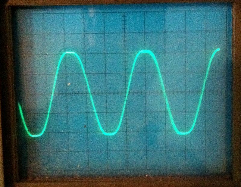
Here's just starting to clip...
[img:800:621]http://theinside.net/twreck/Scoped/1.JPG[/img]

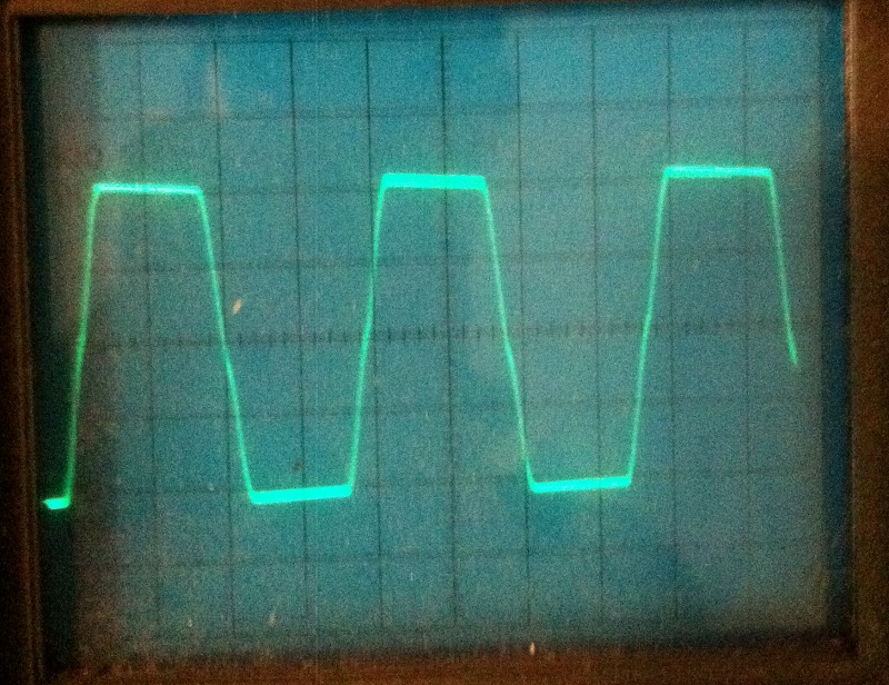
Here's some more drive...
[img:800:616]http://theinside.net/twreck/Scoped/2.JPG[/img]
A lot less crossover distortion
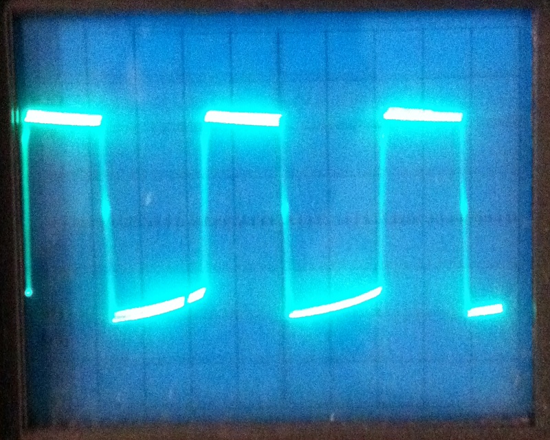
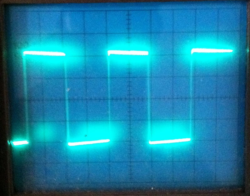
Still more....
[img:800:640]http://theinside.net/twreck/Scoped/3.JPG[/img]
Here we're seeing the widening of the duty cycle on the bottom like the other pics....

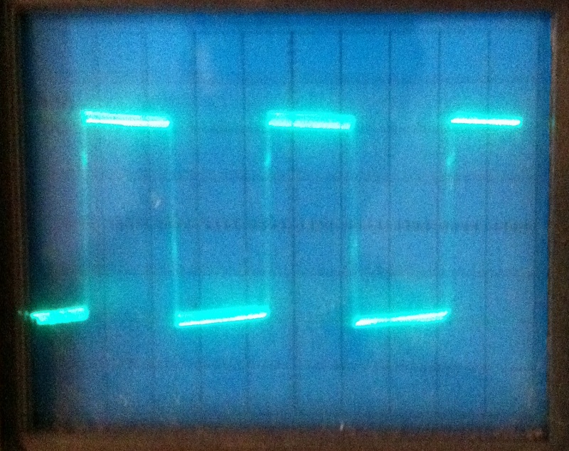
However, things get interesting as we push more...

[img:800:634]http://theinside.net/twreck/Scoped/4.JPG[/img]

It starts to course correct and the crossover notch starts to become less apparent....

Still more drive and...

[img:800:626]http://theinside.net/twreck/Scoped/5.JPG[/img]

looks like a pretty symmetrical square wave with very little crossover distortion notch. It's very narrow on the rise and fall though, like the crossover went from horizontal to vertical...

I was somewhat surprised how different this amp looked.
User avatar
martin manning
Posts: 13207
Joined: Sun Jul 06, 2008 12:43 am
Location: 39°06' N 84°30' W

Re: Express Output Waveform Shots

Post by martin manning »

Good stuff Jackie, thanks for taking the time to do this! Do you know what the third stage was doing as you went up? My thought was that asymmetric clipping there (on the cut-off side) would counteract the widening of the bottom half brought on by the PI.
katopan
Posts: 594
Joined: Mon Aug 22, 2011 10:10 pm
Location: Melb, Australia
Contact:

Re: Express Output Waveform Shots

Post by katopan »

Thankyou so much for posting those CRO shots Jackie. They are exactly what I was after - output waveforms with a scale. Can I ask what frequency did you use and what's the voltage scale on the CRO trace?

I was expecting the bottom half of the wave in pic 3 to have less amplitude, but there you go. I'm setting up my test amp to be able to get a heap of CRO shots of the 3rd stage and PI signals without the power stage connected. This will show everyone what is happening in the PI. Will take a few days to put together but I'll post them here. Things even up again like your pic 4 & 5 not only because of the 3rd stage, but the PI also hits its limits on both sides and becomes just a square wave output. When the output is assymetric like in pic 3 the PI is square on the cutoff side but rounded on the grid clipping side and the operating point of the PI has moved. Drive it harder and the operating point comes back to original bias.
User avatar
rooster
Posts: 1616
Joined: Wed Apr 02, 2008 8:50 am
Location: Pacific NW

Re: Express Output Waveform Shots

Post by rooster »

Thanks Jackie, that is good to see.

And to qualify what I'm seeing in these pics, this is the LTP with a 39K tail, 1K cathode, more feedback, etc.?

If this is the case, are any of you suggesting that the stock Express would scope the same?
Most people stall out when fixing a mistake that they've made. Why?
katopan
Posts: 594
Joined: Mon Aug 22, 2011 10:10 pm
Location: Melb, Australia
Contact:

Re: Express Output Waveform Shots

Post by katopan »

From what I've seen with the standard values there'd be a little bit more assymetry from the warmer bias resistor, and the discharge slope of the lower half of the waveform will be a bit steeper because of the smaller 22nF coupling caps.
katopan
Posts: 594
Joined: Mon Aug 22, 2011 10:10 pm
Location: Melb, Australia
Contact:

Re: Express Output Waveform Shots

Post by katopan »

This took a while to put together, but here is a heap of Express 3rd stage and PI waveform shots. Enjoy!

Jackie - Is there any chance you could get out the CRO again and take similar shots to what you did but of the power valve grids (both sides)? That would fill in the last missing piece of the picture. Would be really appreciated.

*Edit* I re-did the attachment. Noticed that I'd chopped off the scale info of the row of waveform shots at the bottom of the page. Is properly visable now.
You do not have the required permissions to view the files attached to this post.
Last edited by katopan on Mon Sep 05, 2011 11:19 pm, edited 1 time in total.
User avatar
martin manning
Posts: 13207
Joined: Sun Jul 06, 2008 12:43 am
Location: 39°06' N 84°30' W

Re: Express Output Waveform Shots

Post by martin manning »

Nice! I apreciate the effort it took to compile these. At first glance it seems to be in agreement with the discussion above; will be interesting to study a bit more closely.
User avatar
rooster
Posts: 1616
Joined: Wed Apr 02, 2008 8:50 am
Location: Pacific NW

Re: Express Output Waveform Shots

Post by rooster »

katopan - That was an effort, and I thank you.

Now let me ask you a question? If we took the signal generator out and replaced it with a guitar pickup (HB), and we slammed a power chord one time and let it ring out, what do you think we would see on the scope?

My opinion is that we would see your last series of shots, fading into your first series, and perhaps not so evenly. So a real world picture then of the V5 tube experiencing a square wave event - and remaining in a square wave event - while V4 recovers, producing what I refered to at the start of this post as the 'magic' sound of the Express - this lopsided compression delivered by the two output tubes.

Do you agree? Martin, do you agree? All ears here. 8)
Most people stall out when fixing a mistake that they've made. Why?
katopan
Posts: 594
Joined: Mon Aug 22, 2011 10:10 pm
Location: Melb, Australia
Contact:

Re: Express Output Waveform Shots

Post by katopan »

I have looked at the signals while strumming out power chords on a HB guitar. Only trouble is I didn't want to post shots of that because I'm not running a real Express power section and I can only theorize on how it would compare. Can if you want, but gee I'd love to see the real thing. In fact all my research is focused on how to get the levels right to go into a 6P1P or 6BM8 power section. So what I saw with a real guitar signal clearly shows the assymetry (both duty cycle and height) shift back into being symmetrical and then fading into clean. You can also see some suppression of the higher frequencies from the clipping, and then they come back as it fades and cleans up again. I think part of the magic of the tone is that the cleans and edge of overdrive is nice and symmetrical, then as the distortion increases just to the point where any other amp becomes a harsh sounding square wave this introduces the assymetry effectively adding a heap of 2nd order harmonics and warming up the tone of the distortion. Other amps that overdrive a preamp stage to get some assymetry still have the assymetry clean, and symmetrical preamps just driving a heap into a push-pull power stage end up sounding harsh when they get to this level of distortion. That's from a tone point of view.

Clean to mean I still haven't found an explaination I'm happy with. Was hoping the reduction in the height of the lower half output waveform would be the reduction in overall amplitude needed to make the means the same volume as the cleans. But looking at both Jackie's and John Polstra's shots it's not enough and there's no real sag in the power clipped amplitude with increasing overdrive (if anything it goes up a bit). With the 6P1P or 6BM8 versions I'm getting the tone but not the clean to mean, and have explored the effects of the assymetry, power B+ sag, screen supply sag, pentodes vs beam tetrodes, various levels of PI output into the power section via split plate PI resistors, and changing power grid coupling caps to get more discharge slope on the V4 side.

I was going to draw a line on the power grid resistor signal shots of where the EL34 grid clipping threshold was, but it's not so simple to work out with all the dynamics happening. Shifting of the power grid coupling cap voltages cools off the bias (thanks Jackie - I was wrong about no bias shift with fixed bias) seen by the cross-over distortion. From the EL34 datasheet cutoff with 400V plate & screens is around -50V. With the 6k6 OT sitting below the shoulder of the pentode curve, the grid voltage won't go much more than 0V with clipping. So you could draw a line at 50V above the bias centre line to overlay the clipping threshold with the unloaded PI output waveform. But this doesn't account for 40-50V screen supply sag effecting both the power grid threshold and the PI output swing. Also I don't know if the V4 side backs off below power grid clipping enough for C9 to loose the change in bias (but not the C10 side) which would in turn reduce that clipping threshold to just the difference between the bias and 0V (around 33V), or not.
User avatar
martin manning
Posts: 13207
Joined: Sun Jul 06, 2008 12:43 am
Location: 39°06' N 84°30' W

Re: Express Output Waveform Shots

Post by martin manning »

rooster wrote:If we took the signal generator out and replaced it with a guitar pickup (HB), and we slammed a power chord one time and let it ring out... My opinion is that we would see your last series of shots, fading into your first series...
Absolutely. And all this happens because the PI and power amp are driven very hard even at low volume settings and signal levels. I guess you could say the magic is that you can get to that point without a lot of fizzy preamp distortion cluttering it up. I think this is the explanation for the clean-to-mean phenomenon too. A low signal level of say 50mV produces a clean output of say 20V p-p, but 100mV is enough to square the output, and since the threshold of clipping is immediate, the output is still at 20V p-p. I think that is what Jackie's scope shots are showing, if the increase in "drive" is an increase in the input signal level. This would seem to depend on the volume knob setting too, so maybe the effect is most noticeable around a sweet-spot where the power amp is just below clipping at some nominal input level.
Post Reply