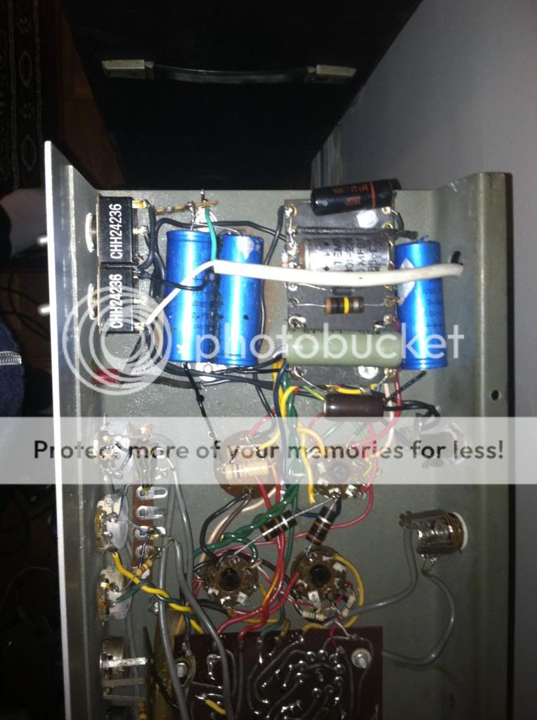
Here is a gut shot of the G150, from which you can make out most of the wires and figure out what they are... hope this helps.
[img:764:1024]http://i885.photobucket.com/albums/ac56 ... dbada8.jpg[/img]
Stancor transformer
Moderators: pompeiisneaks, Colossal

Re: Stancor transformer
The only way to know for sure which leads are what is to plug the thing in and test. This is a very simple test, and it should be safe. I suggested the screw down terminals so you aren't dealing with flying leads getting out of control.
My take on it is:
Primary: Black-Black
HV Secondary: Red-Red/Yellow-Red
6.3V: Green-Green/Yellow-Green
5V: Yellow-Yellow
I don't think there is a bias tap on this one. That's not to say I'm right about that. It's an educated guess.
You are measuring AC volts.
On the HV Secondary, you should see the full amount Red to Red, and half that Red to Red/Yellow. If that is what you see, then Red/Yellow is the center tap. If it is more like 50V to one Red and lots more to the other then it is a bias tap.
I don't like that the green on the Green/Yellow doesn't match color-wise. It may be nothing at all. The check for the CT is same as above. 3.5V to the CT and about 7V across the two Greens. (Unloaded voltage will be higher than 6.3V.) If you have no continuity on the Green/Yellow, it could be a bias tap. Then I'd check it to each Red wire.
There is every good reason to lengthen these wires. I make a splice and cover with heat shrink. Use the right gauge of wire and make the extensions longer than you imagine you want them. This way, you won't be forced to cut off more of the original to get a good do-over splice.
I wish I could see more in that picture posted by Jazbo. The reds are more or less lost for me.
Re: Stancor transformer
Wow.....Jess Oliver.!matt h wrote:5K into 8/16 ohms?
Well, if it's a conservative 25 hi-fi watts, that sounds like a good platform for a 4xEL84... just keep the plate supply voltage under 300V.
You could do a pair, but you'd be stuck running a 16ohm load on the 8ohm tap, not very useful.
That isn't really a good OT for a pair of 6L6GC, but would be killer for old school 6L6G/5881 types running at low voltage. Don't plan on more than 30-35W.
Is there a schem for this amp.?
Going with Matt's numbers.......maybe he could build a Soldano 25 clone.?
-------------------------------------
https://www.youtube.com/watch?v=zhvDOxvfvhw
https://www.youtube.com/watch?v=KWXulD-gxuw @ 1:40
https://www.youtube.com/watch?v=iTxaQu4NfI8
https://www.youtube.com/watch?v=_BSCS_hl0iA
https://www.youtube.com/watch?v=zhvDOxvfvhw
https://www.youtube.com/watch?v=KWXulD-gxuw @ 1:40
https://www.youtube.com/watch?v=iTxaQu4NfI8
https://www.youtube.com/watch?v=_BSCS_hl0iA

Re: Stancor transformer
Actually, the amp that these trannies came from was 45 - 50 watts. I just ordered a slew of parts for a Super Reverb which, if these are the right fit, I'll be building a clone of.
Stay tuned
Stay tuned
Re: Stancor transformer
(deleted)
Last edited by matt h on Fri Mar 27, 2015 2:59 pm, edited 1 time in total.
Re: Stancor transformer
I'm a little out of my depth in this comment, so it is really a question. It seems to me in AB1 for a pair of 6L6GC, plate voltage over 400, you might be able to tune it to 75mA per side, getting into the 40-50W range. At lower voltage, current will want to rise too high for this OT. I wish I knew and understood the math for this. I am thinking there is a way to back into the 75mA rating with a satisfactory solution for a ~45W amp.
Re: Stancor transformer
(deleted)
Last edited by matt h on Fri Mar 27, 2015 3:08 pm, edited 1 time in total.
Re: Stancor transformer
If the transformers really came out of the G150, then they can probably handle a bit more than 25W. The G150 was rated for 35Wrms and 90Wpmp! So they can be pushed a bit... But since the OP does not want to build with the 6L6GC (which was used in the G150), then I guess try EL34, 5881 or quad EL84, ditto for their Russian equivalents? Lots of options...
Ohm readings from power transformer
Black (Primary) - 1.2 ohms
Red 1 (high voltage) and center tap - 46.3
Red 2 and center tap - 51.3
Yellow - .2
Green 1 and center tap - .1
Green 2 and center tap - .1
Red 1 (high voltage) and center tap - 46.3
Red 2 and center tap - 51.3
Yellow - .2
Green 1 and center tap - .1
Green 2 and center tap - .1
Re: Stancor transformer
I'm seeing that possibly the yellow is the 5volt and green is the 6 volt
Re: Stancor transformer
Green is likely 6.3 and yellow 5. The number of turns (length of he wire) is about the same, but the wire gauge on the 5V is bigger. Also, these are standard colors.
1.2 ohms on the primary suggests the PT is rated about 300VA. To translate this to the secondary, we'd need to know more but we can always guess. Figure 5V @ 3A = 15VA, 6.3V@4A = 25VA. If total is 300VA, that leaves 260VA for the high voltage secondary more or less.
We will need to know the secondary voltage (loaded) to get an idea of the mA rating. The lower the voltage, the higher the mA. Let's make a simple example/guess we have 250VA and the secondary is 750V (375-0-375). 250/750 = 333mA. I'm guessing this is at or near the upper end. You should have plenty of juice to run a pair of most of the common octal output tubes.
Do we know the tube compliment of the donor amp? That would help a great deal in making an educated guess.
Re: Stancor transformer
2 x 7027a
1 x GZ34
3 x 6EU7
1 x 6AN8A
1 x GZ34
3 x 6EU7
1 x 6AN8A
Re: Stancor transformer
The G150r had no gain structure - purely a clean amp. I've read that the 6EU7 tubes had more gain than 12ax7s, but I could be wrong - semi-green here. the 6AN8A and one 6EU7 were in the reverb/tremolo (tremelo) section.
Re: Stancor transformer
Just by the readings, I'm assuming that the trannies would be ideal for the Super Reverb build. Powering 6l6g tubes and a handful of 12ax7s and 7025s
Re: Stancor transformer
The GZ34 needs 1.9A. I was hoping it had a 3A rectifier. We know the PT can handle the 2A rectifiers. More than that is an open question. GZ34 is good, though.
On the 6.3V you had 4x .3A + .45A. That's 1.65A plus the power tubes. 6L6's? That's another .9 x 2 for a total of 3.45A. Allow a little something for a pilot...3.5-3.6A probably. More, without the spec, we don't know.
We don't know the operating parameters of the output tubes. Power it up and tell us the unloaded VAC reading across the two reds. I'll guess 200mA for the power tubes and 35-40mA for the other tubes. That gets us into the 240mA ballpark I was guessing at.
There is NO FUNCTIONAL DIFFERENCE between 12AX7 and 6EU7. They have a different pin out and you can't run 6EU7 heaters on a 12.6V supply. Look up the tube specs.
Given the old tube line up, I'd agree you can do the SR. The only question is what will B+ be? Plug that thing in. The suspense is killing me!