martin manning wrote: ↑Sun Aug 12, 2018 11:14 am
You can always use the DC resistance of the OT primary to get idle current: Just measure Ra-ct on both sides (resistance from CT to plate) with power off, and then measure the voltage drop across the same two points on each side with power on. Current is (Va-Vct)/(Ra-ct).
Of Course! Brilliant! - sounds like a good exercise. That would measure plate dissipation only - yes?
I'll try that for my present resistor pair (470 & 27K) and see what's happening.
Thank you (again) sir!
Will post results after breakfast
-Paul
So - here's what I found...
Tube A: R = 48.1 Ohms; V = 1.35; I = 28 mA
Tube B; R = 45 Ohms; V = 1.21; I = 26.9 mA
This is more dissipation than I thought I would find - but definitely need to be able to adjust higher. Wouldn't you agree?
martin manning wrote: ↑Sun Aug 12, 2018 1:57 pm
So you want to see 1.92V on the tube A side. The B+ will drop a bit after you increase the current, so you might recalculate and do it again.
Gotcha. I'll run a few iterations and post what I settle on.
Once you have set the bias to provide your desired dissipation, it would be useful to measure the negative bias voltage on pin 5 of each power tube and write that number on the schematic for future reference. I like to have voltages for all tube pins on my schematics.
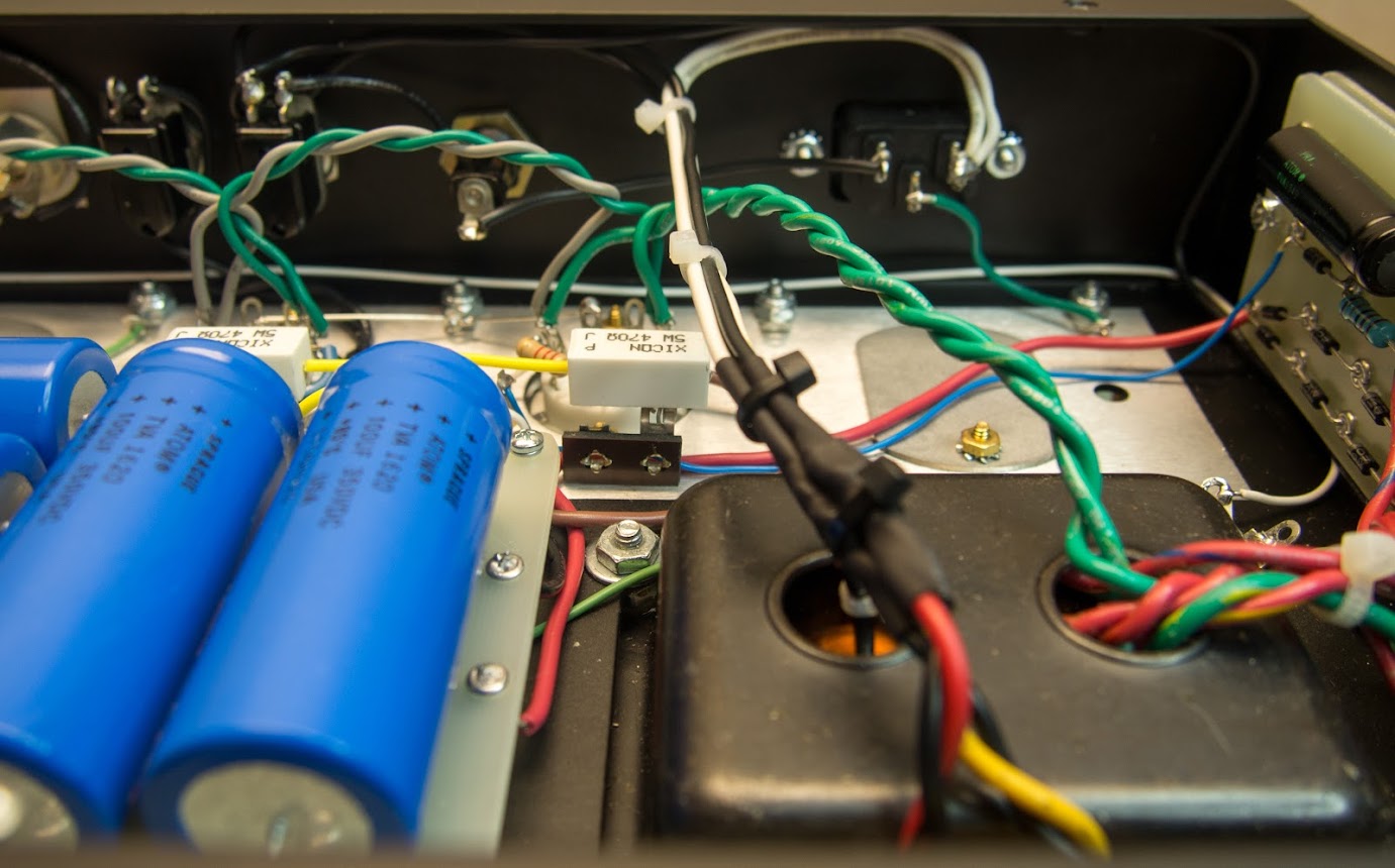
So - I settled on a 1.8K "pre-diode" resistor value. The resistor to ground off of the trim pot is the original 27K.
That gives me a bias voltage range of -41.5 to -54.8
I was able to get My "tube A" right on target dissipation (40.3 mA) with -44.35 bias voltage on pin 5. So, I could go some hotter - and quite a bit colder.
This put the plates @ 447 and screens @ 446.
All of the controls and switches seem to function as intended. Amazing tonal breadth with the tone switches.
all the 6L6 Dumble builds I've done all seem to bias around the 43mv mark. So much so that's what I aim for now when powering up and just tweak from there.
Bear in mind even with so called matched valves there can still be ~5 mv difference in valves so you have to have a happy average anyway, it's not precision engineering here
norburybrook wrote: ↑Sun Aug 12, 2018 6:46 pm
all the 6L6 Dumble builds I've done all seem to bias around the 43mv mark. So much so that's what I aim for now when powering up and just tweak from there.
Bear in mind even with so called matched valves there can still be ~5 mv difference in valves so you have to have a happy average anyway, it's not precision engineering here
glad you're up and running, it's a great feeling.
MC
Thanks!
Me too (glad to be up and running). The only real issue that I had - was with the bias circuit (as you may have followed in this thread). Which is surprising to me (that there would be a problem with that) - but grateful for the learning opportunity and grateful to those here that provided the learning.
I am aware that setting the bias doesn't need to be an exacting affair - but was being precise here more because of the change needed to the bias circuit - and communicating to Martin and slucky exactly what I was seeing and doing.
With something around 450V on the plates, the current will always be around 40 mA for a reasonable plate dissipation, but the bias voltage required to make that happen will vary plus or minus a few volts due to variation in the output tubes. I don’t know how much difference there is in the VAC at the bias tap from one Fender Twin transformer manufacturer to the next, but with the typical 10k pot limiting the adjustment range, there is always the possibility that some tweak will be needed to get the DC voltage in the right range.
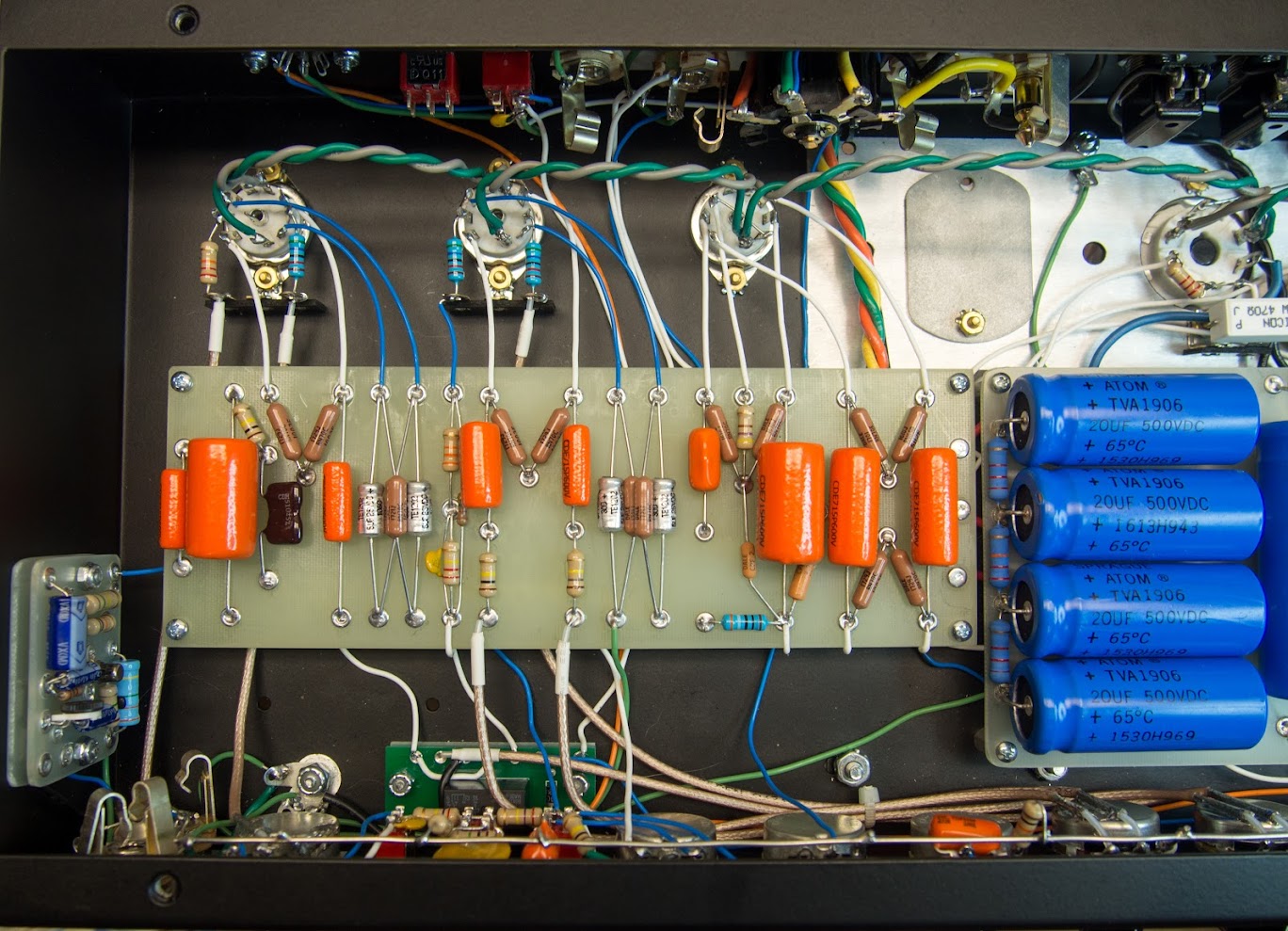
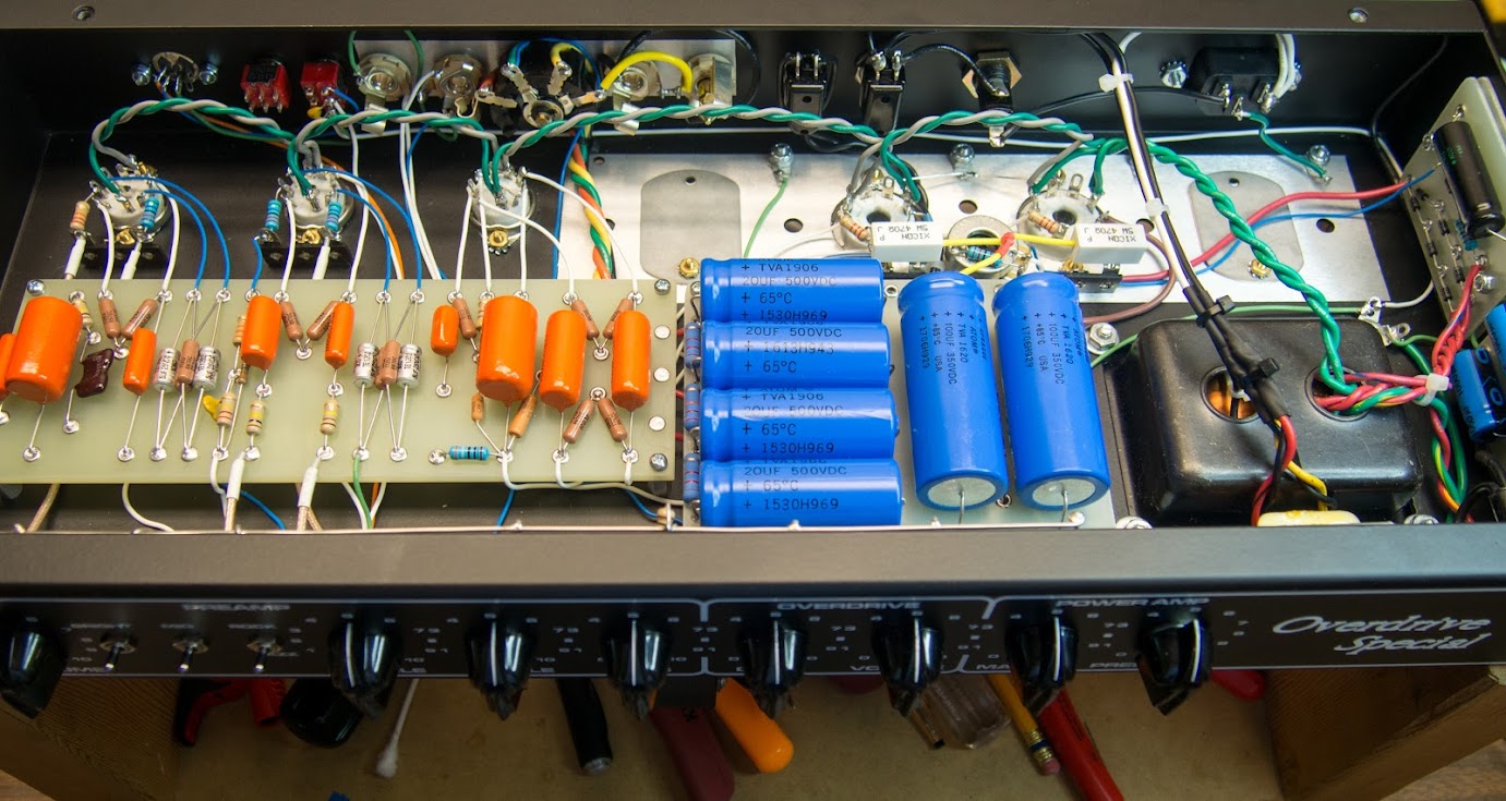
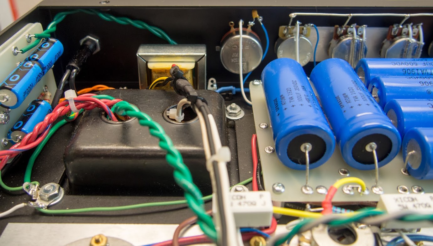
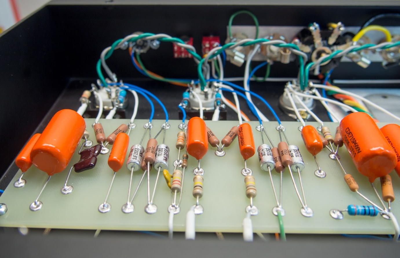
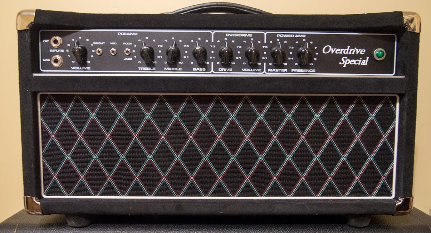
Here are the final build pics - including one in the beautiful head-shell built by Taylor at Amplified Nation. I have an EVM-12L waiting on a matching single 12 cab.
Again - many thanks to those that contribute their time and knowledge so generously
-Paul
amplifiednation wrote: ↑Tue Aug 14, 2018 1:48 am
Looks great Paul! I like what you did with those cathode resistors.
Thanks Taylor!
I'll take that as extra high praise coming from you.
I played it a little this evening and I was surprised how articulate that rascal is. That was using a Marshall JCM900 combo as the speaker cab (2xG12T-75) - and a Les Paul. I think that EVM12L will be a better speaker choice and I think Fender or a semi-hollow would be better matched. It makes you focus a bit more on technique - as you can hear everything very clearly.