In looking at the TW Express Version A1b schematic, I notice that the 1k dropping resistor from B1 to B2 is 25w. Why is it so big? By my calcs, I get:
dV = Vb1 - Vb2
= 295 - 380
= 15
I = V / R
= 15V / 1000ohms
= 0.015 Amps
P = I V
= 0.015A * 15V
= 0.225 W
Did I calculate something wrong here?
thanks
Don
Why is the B1-B2 dropping resistor so darn big?
Moderators: pompeiisneaks, Colossal

Re: Why is the B1-B2 dropping resistor so darn big?
V in the second calculation is 380V not 15V. I=.039A
W=14.44
25W is the next size up. Trust me, even 25W gets a little warm there!
W=14.44
25W is the next size up. Trust me, even 25W gets a little warm there!
Re: Why is the B1-B2 dropping resistor so darn big?
Thats kinda got me puzzled!  if V in the calculation is 380V surely your saying the resistor is dropping the entire B+!
Its only dropping 15V, sure it'll drop more flat out but surely not the entire supply!
Its only dropping 15V, sure it'll drop more flat out but surely not the entire supply!

Re: Why is the B1-B2 dropping resistor so darn big?
Your formulas are right but you calulations are wrong 380v-295 is 85v not 15. 85/1000=.085 or 85 ma. .085x 85=7.25 watt. A 10 watt would do but a 25 watt will last forever in this circuit. The cost for the added reliability is just a few cents difference in price between the 10w and the 25.
Re: Why is the B1-B2 dropping resistor so darn big?
Interesting...
Okay, this thread has me checking the math in my AC30 build regarding the B+ dropping resistor.
I've used this one:
http://www.vishay.com/docs/30201/rhnh.pdf
I used a Dale RH-10, 10w aluminum housed mil spec 121 ohm resistor that can be switched into the B+ line in order to drop voltage after the recto (5AR4). As it stands now, with the resistor switched into the circuit, the voltage on the recto side of the resistor is 333v. After the resistor, it is 310. So, we're dropping 23v. I did the math, and it came out like this:
dV = Vb1 - Vb2
= 310 - 333
= 23
I = V / R
= 23V / 121ohms
= 0.19 Amps
P = I V
= 0.19 * 23V
= 4.37 W
Does this all look correct? Am I then safe with a 10w mil spec aluminum housed resistor in there, especially being as it is conservatively rated at 10w (it is really closer to a 12.5w resistor, due to it's construction)? That's almost three times the rated wattage, so I think that's okay...just looking for a little reassurance (newbies like that sort of thing...). It gets pretty warm, but it has it's own heat sink, and I have it bolted down to the chassis with some high-quality, silver thermal grease between it and the chassis.
Also, when I measure the voltage on the 1st cap after the recto (after the resistor....), without the resistor I get 356v, with the resistor in the circuit, I find 310v. Measuring on the recto pin itself, with the resistor engaged I'm reading 333v, with it disengaged, I'm seeing the 356v again. Does this mean I'm actually dropping 45v across the resistor, or am I seeing something else when I switch in the resistor? With the resistor engaged, on one side of the resistor I'm reading the 333v and on the other side of it I'm seeing 310v, so I ASSUME that I am indeed only dropping 23v....but I many be wrong...
Thanks!
Last edited by dehughes on Sat Mar 24, 2007 5:20 pm, edited 1 time in total.
Tempus edax rerum
Re: Why is the B1-B2 dropping resistor so darn big?
You got to remember that you are measuring the voltage drops with the amp just sitting there with no signal. When you crank it up these values will change. As you draw more screen / preamp current these voltage drops will go up some so you may want to check it with a signal applied and the amp hooked to a dummy load to get an accurate reading.
Re: Why is the B1-B2 dropping resistor so darn big?
This is with the amp on and plugged into the speakers, etc.... Is that fine?UR12 wrote:You got to remember that you are measuring the voltage drops with the amp just sitting there with no signal. When you crank it up these values will change. As you draw more screen / preamp current these voltage drops will go up some so you may want to check it with a signal applied and the amp hooked to a dummy load to get an accurate reading.
Tempus edax rerum
Re: Why is the B1-B2 dropping resistor so darn big?
edit...
Last edited by dehughes on Sat Mar 24, 2007 5:40 pm, edited 1 time in total.
Tempus edax rerum
Re: Why is the B1-B2 dropping resistor so darn big?
Yes either a speaker or dummy load but with the amp just on and not amplifing anything you are only measuring the drop accross the resistor with no input. As you crank the amp with a signal supplied the vlotages will change as the current flow through the resistor increases.dehughes wrote:This is all with the amp on and plugged into the speakers, etc.... Is that fine?UR12 wrote:You got to remember that you are measuring the voltage drops with the amp just sitting there with no signal. When you crank it up these values will change. As you draw more screen / preamp current these voltage drops will go up some so you may want to check it with a signal applied and the amp hooked to a dummy load to get an accurate reading.
Re: Why is the B1-B2 dropping resistor so darn big?
Thanks man. So are you saying that a larger resistor is in order, most likely?UR12 wrote:Yes either a speaker or dummy load but with the amp just on and not amplifing anything you are only measuring the drop accross the resistor with no input. As you crank the amp with a signal supplied the vlotages will change as the current flow through the resistor increases.dehughes wrote:This is all with the amp on and plugged into the speakers, etc.... Is that fine?UR12 wrote:You got to remember that you are measuring the voltage drops with the amp just sitting there with no signal. When you crank it up these values will change. As you draw more screen / preamp current these voltage drops will go up some so you may want to check it with a signal applied and the amp hooked to a dummy load to get an accurate reading.
Tempus edax rerum
Re: Why is the B1-B2 dropping resistor so darn big?
I always assumed that the 1K/25W was used to help smooth ripple, much the same as a choke. Does the size (in wattage) have anything to do with that? (wire size, number of turns, etc.)
Re: Why is the B1-B2 dropping resistor so darn big?
Even if it was a wire wound resistor, I doubt there would be enough inductive reactance to make a difference.. Why 25w? I really don't know unless Ken figured 10W just wasn't enough and the next size up was a 25w. (Pure speculation on my part) I think the biggest part that this resistor plays is setting the screen current /voltage. You do get the current draw from the 3 12ax7s added into the equation but they draw very little current.Normster wrote:I always assumed that the 1K/25W was used to help smooth ripple, much the same as a choke. Does the size (in wattage) have anything to do with that? (wire size, number of turns, etc.)
One thing interesting to note is that on the Liverpool Ginger, Ken used a 10W 1k resistor. Then he turns around and does something wierd. Since Ginger used a 1/2 power switch and is cathode biased, Ken used two 130 ohm cathode resistors. One was 10w and the other was 25W. I think he used a lot of what he had laying around
Re: Why is the B1-B2 dropping resistor so darn big?
To add to what Dana said, it is *just* the R/C filtering of 1000 ohms followed by the screen filter cap in play here. If you made a big 25 watt resistor out of multiple 1w carbon films (or a long piece of resistance wire), it would have the same effect at audio frequencies as the one big cement one. The size doesn't have a lot to do with it's effect in the circuit, and as Dana said, the inductance is negligible.Normster wrote:I always assumed that the 1K/25W was used to help smooth ripple, much the same as a choke. Does the size (in wattage) have anything to do with that? (wire size, number of turns, etc.)
Of course, the stray reactances due to a physical 'resistor bird cage' made out of 25 CF resistors may have an aural effect!
--mark
Re: Why is the B1-B2 dropping resistor so darn big?
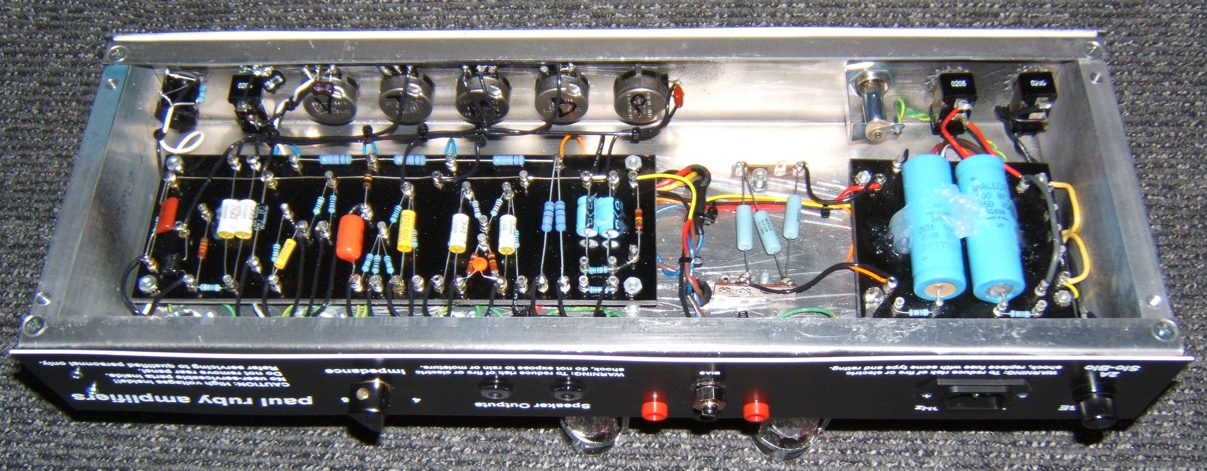
FYI... I've used 1k 10W in some builds, which are fine, but they run very hot and need plenty of air space around them. On this particular build, I used three series 330ohm 5W each to get air space:
http://www.paulamps.com/MartaGuts.jpg
I originally had a 1k 10W on the black turret board and it got hot enough to blister the board! No way could I leave that sitting next to the filter caps. You can tell from the wiring that the terminal strips were a later add and you can see the wire jumpers up to the power supply board.
A 25W resistor will run cooler and last longer but still will be putting out just as much heat (power dissipation is the same) so you still need some air space around it.
-
oldepicker
- Posts: 32
- Joined: Thu Mar 30, 2006 4:33 pm
- Location: Concord, NH
- Contact:
My own blasphemous take...
Hi guys, I was lurking a while last year, but got real busy with gigs and other assorted work and play, but was also giving thought and making some notes and plans for my own build. This resistor discussion kind of got me all wound up again and also made me wanna ask about a choke, or lack thereof. I just last night finished my own slightly modded FRANCESCA based amp. As an aside, the thing absolutely SMOKES!!!
I tend to agree with the assertion that Ken may have at times been a bit of a scrounger ( Dumble seemed to be too, if what I hear about the broad range of components and suppliers he may have utilized is true when a few ODS amps are opened for inspection). I love the discussions about each and every minute detail being part of the elusive "mojo" that is Trainwreck. Some pieces I think were simply laying around and would work, so in it went. I'd love to get some feedback on why not to use a choke.
The few amps I've swapped chokes into that had "the big ass" resistor always sounded better.
So...my amp is a 6V6 powered, GZ34/5AR4 rectified, Mercury Magnetic Fender BF Deluxe Reverb Transformered creation and I used a Super/Vibroverb 40W size choke instead of the smaller one in the Deluxes- it's rated at 90ma and 1.5K as opposed to 50ma and 1.5K of the smaller one(I forget how many Henries). I used some really cool paper in oil 1000v 0.015uf in place of the 0.022's in the original circuit. The 0.0022uf cap coming out of the 2nd stage got swapped to a 0.0068uf p.i.o. 1600v cap to tame some of the treble I have introduced w/ the cap changes I did. The next 0.1uf cap is a 0.047uf auricap. I love the sound and it's pretty quiet. I haven't even swapped in the "good" tubes yet (just in case it blew up with the initial power up!). I'm running a Chinese Sino 5AR4 that I pulled out of a Bruno UG30 I had, an NOS pair of Zenith coin base 6V6's, and 3-12AX7A/7025 Sovteks that are my testing tubes-but sound pretty decent.
I may try to get some photos up soon, but am pretty busy with gigs and stuff. The same with clips (if I can figure out how to do it!).
I mounted all my electrolytics on top on a breadboard on standoffs.
I'm STILL too loud???