The deeper I get into this build and the more components that get added to the chassis the more I realize this is an art and I am a novice.
Issue #1 PT and choke mounting nuts will not allow filter caps to fit. Is it okay to mount the 20's on the bottom and the 40's on top? the 20's will fit between the nuts. I could also set the stack diagonal but that looks funny.
Issue #2 There are 5 pairs of wires coming from the PT. 2 pairs go to rectifier, 1 pair goes to V7, 1 pair goes to power switch. Does it matter what goes where. The gray wires that go to rectifier for example go to pins 2 and 8. The greens with yellow strip go to pins 4 and 6.
Issue #3 Does the lamp have polarity? Does it matter how I wire it to the power switch?
Issue #4 The ground/black wires from the 20 and 40 filter caps are shown to go the the rectifier and are soldered to tabs. My rectifier socket is a Belkin style and it does not have tabs. Is it okay to place a grounding lug under one of the mounting nuts and ground both the 20 and 40 filter caps there?
Why are they grounded to the rectifier socket and not elsewhere?
DONNA ROCKET build issues
Moderators: pompeiisneaks, Colossal

Re: DONNA ROCKET build issues
Greg,
Will try to give you the answers.
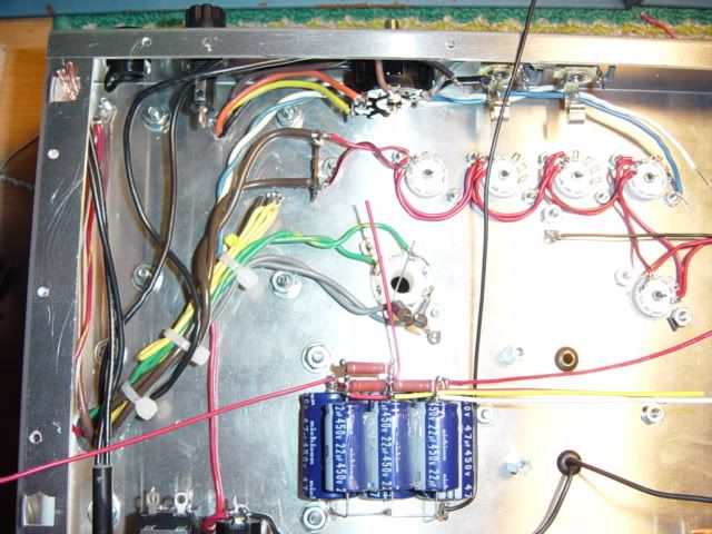
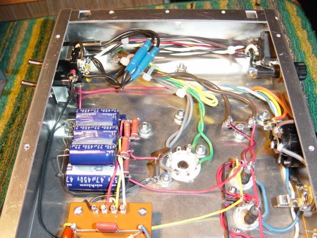
#1 Here are a couple of pictures 1 showing the cap stack, 1 showing the wiring bundle. the cap stack should fit between the transformer screws with room next to the choke screw.
[IMG:640:480]http://i405.photobucket.com/albums/pp13 ... C00401.jpg[/img]
#2 No you should be able to wire them in pairs as you listed, no polarity issues. Shrink wrap the ends of the unused wires, they can be cut off shorter or leave them long and tie them into the bundle in case you ever need them in another build.
#3 The lamp has no polarity. I used some butt end connectors for mine as I did not want to resolder it to put my faceplate on. It will make it easier to replace if it blows someday (no soldering).
[IMG:640:480]http://i405.photobucket.com/albums/pp13 ... C00415.jpg[/img]
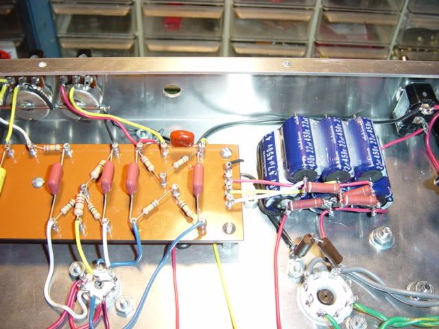
#5 Yes, put the solder lug there, I also put my bleeder resistors there coming off the pin on the recto that goes to the cap stack.
[IMG:640:480]http://i405.photobucket.com/albums/pp13 ... C00412.jpg[/img]
Hope I helped.
Gary
Will try to give you the answers.
#1 Here are a couple of pictures 1 showing the cap stack, 1 showing the wiring bundle. the cap stack should fit between the transformer screws with room next to the choke screw.
[IMG:640:480]http://i405.photobucket.com/albums/pp13 ... C00401.jpg[/img]
#2 No you should be able to wire them in pairs as you listed, no polarity issues. Shrink wrap the ends of the unused wires, they can be cut off shorter or leave them long and tie them into the bundle in case you ever need them in another build.
#3 The lamp has no polarity. I used some butt end connectors for mine as I did not want to resolder it to put my faceplate on. It will make it easier to replace if it blows someday (no soldering).
[IMG:640:480]http://i405.photobucket.com/albums/pp13 ... C00415.jpg[/img]
#5 Yes, put the solder lug there, I also put my bleeder resistors there coming off the pin on the recto that goes to the cap stack.
[IMG:640:480]http://i405.photobucket.com/albums/pp13 ... C00412.jpg[/img]
Hope I helped.
Gary
In the 60's people took acid to make the world weird. Now the world is weird , and they take Prozac to make it normal.

Re: DONNA ROCKET build issues
There is so much room in a Rocket compared to the Liverpool or Express and I will attach a picture of my Rocket it may help. You may need to camfer a hole and change over to a different style machine screw head to clear the caps.
Mark
Mark
You do not have the required permissions to view the files attached to this post.
-
RJ Guitars

- Posts: 2663
- Joined: Tue Nov 14, 2006 3:49 am
- Location: Los Alamos, New Mexico
- Contact:
Best way to mount your filter caps
Greg,
I've seen this quite a few times and there are a couple good ways to get a little more flat space. One of the better ones is to change the power tranny screws to flat-heads, mounted from the inside going to the outside.
That will open up enough real estate so that even those old Monster Sprague caps will go in there.
My personal preference is not to glue caps to the chassis... but that is a different issue...
rj
Good, Fast, or Cheap -- Pick two...
http://www.rjguitars.net
http://www.rjaudioresearch.com/
http://diyguitaramps.prophpbb.com/
http://www.rjguitars.net
http://www.rjaudioresearch.com/
http://diyguitaramps.prophpbb.com/

Donna Rocket
#5 Yes, put the solder lug there, I also put my bleeder resistors there coming off the pin on the recto that goes to the cap stack.
 Are these poly caps "Panasonic" . I used them in my Rocket and think they sound great . Any one else compared these and the "Orange drops" for a taste test ??
Cam
Cam
Macshaft:)