
I can't see from your pictures exactly what is happening, but there is one trap that is easy to fall into with these relays: the three pins that comprise the switch are NOT oriented the same way they would be on a switch.
On a switch, the common terminal is typically in the middle, and connects with the outer terminals.
On these relays, the common terminal is the one closest to the coil terminals.
If you don't remember that, it can be embarrassing. Ask me how I know.
HTH,
footswitch problems
Moderators: pompeiisneaks, Colossal
-
dcribbs1412
- Posts: 1378
- Joined: Wed Jun 11, 2008 6:56 pm
- Location: Arizona Desert
Re: footswitch problems
Thanks greiswig
I understand...I am a little lost in the relay footswitch thing
is there a particular layout I could look at to check?
I've looked at a few but most differ slightly(124 ctone BM)
I will try to post better pics
I understand...I am a little lost in the relay footswitch thing
is there a particular layout I could look at to check?
I've looked at a few but most differ slightly(124 ctone BM)
I will try to post better pics
Re: footswitch problems
FWIW.. Here is a footswitch diagram I've implemented on some of my 2 channel stock switching....If you want you can add on an extra wire for a 3rd switch and led (and the resistors for LED's)..If you are going with just the 2 you can use a stereo jack and go with the 1/4 inch stock stereo plug on the Marshall switch..BTW dont forget to reverse the LED leads
Hope this helps!!
Tony
Hope this helps!!
Tony
You do not have the required permissions to view the files attached to this post.
" The psychics on my bench is the same as Dumble'"
-
dcribbs1412
- Posts: 1378
- Joined: Wed Jun 11, 2008 6:56 pm
- Location: Arizona Desert
Re: footswitch problems
Thanks so much Tony
I will give this a go ASAP
Thanks
I will give this a go ASAP
Thanks
Re: footswitch problems
Relay wiring can be confusing.
This may be late to the game but when I built my amp and used J. Border's relay pcb's I made these drawings to go by.
The top picture in each is like the way Dumble did it, then below is how to wire it using the Border pcb.
This may be late to the game but when I built my amp and used J. Border's relay pcb's I made these drawings to go by.
The top picture in each is like the way Dumble did it, then below is how to wire it using the Border pcb.
You do not have the required permissions to view the files attached to this post.
Tom
Don't let that smoke out!
Don't let that smoke out!
-
dcribbs1412
- Posts: 1378
- Joined: Wed Jun 11, 2008 6:56 pm
- Location: Arizona Desert
Re: footswitch problems
Cool thanks so much Tom
this will help me check my work
I think I have some changes to make
no ground on the PAB?
dotted lines on OD relay are underboard jumpers?
this will help me check my work
I think I have some changes to make
no ground on the PAB?
dotted lines on OD relay are underboard jumpers?
Re: footswitch problems
Sorry, I drew these for my own use so the notation isn't real obvious.
The dotted lines on the OD relay show how it is to be connected, you can do it either way.
I put a short jumper on top of the pcb where the dotted blue line is.
The only ground on the PAB is the on the bottom of the relay coil which is where the wire to the rear panel switches and footswitches go.
Remember, we are turning on the relays by completing the circuit to ground.
Tom
Don't let that smoke out!
Don't let that smoke out!
Re: footswitch problems
Here is the relay I was talking about. What I was saying is to note that pins 4 and 6 are normally closed, but pins 4 and 8 are in contact when the relay is energized. This is a bit counterintuitive when compared to a normal switch, which (if the three pins were numbered the same) would NEVER have pins 4 and 8 in contact: only either 6 and 4 or 6 and 8.dcribbs1412 wrote:Thanks greiswig
I understand...I am a little lost in the relay footswitch thing
is there a particular layout I could look at to check?
I've looked at a few but most differ slightly(124 ctone BM)
I will try to post better pics
HTH,[/img]
You do not have the required permissions to view the files attached to this post.
-g
-
dcribbs1412
- Posts: 1378
- Joined: Wed Jun 11, 2008 6:56 pm
- Location: Arizona Desert
Re: footswitch problems
Thanks greiswig
This will help
This will help

did it this way
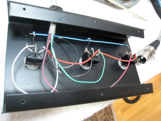
Here are some more pics of a foot-pedal that has OD, PAB Mid-boost
pink - PAB, White - mid, Black1 - OD, green - ground, Black 2 - B+
red jumpers daisy chained for ground. 1K dropping resistors on LEDS.
[IMG 1152]http://i260.photobucket.com/albums/ii9/ ... G_1326.jpg[/img]
[IMG:640:480]http://i260.photobucket.com/albums/ii9/ ... G_1327.jpg[/img]
[IMG 576]http://i260.photobucket.com/albums/ii9/ ... -deric.jpg[/img]
pink - PAB, White - mid, Black1 - OD, green - ground, Black 2 - B+
red jumpers daisy chained for ground. 1K dropping resistors on LEDS.
[IMG
 1152]http://i260.photobucket.com/albums/ii9/ ... G_1326.jpg[/img]
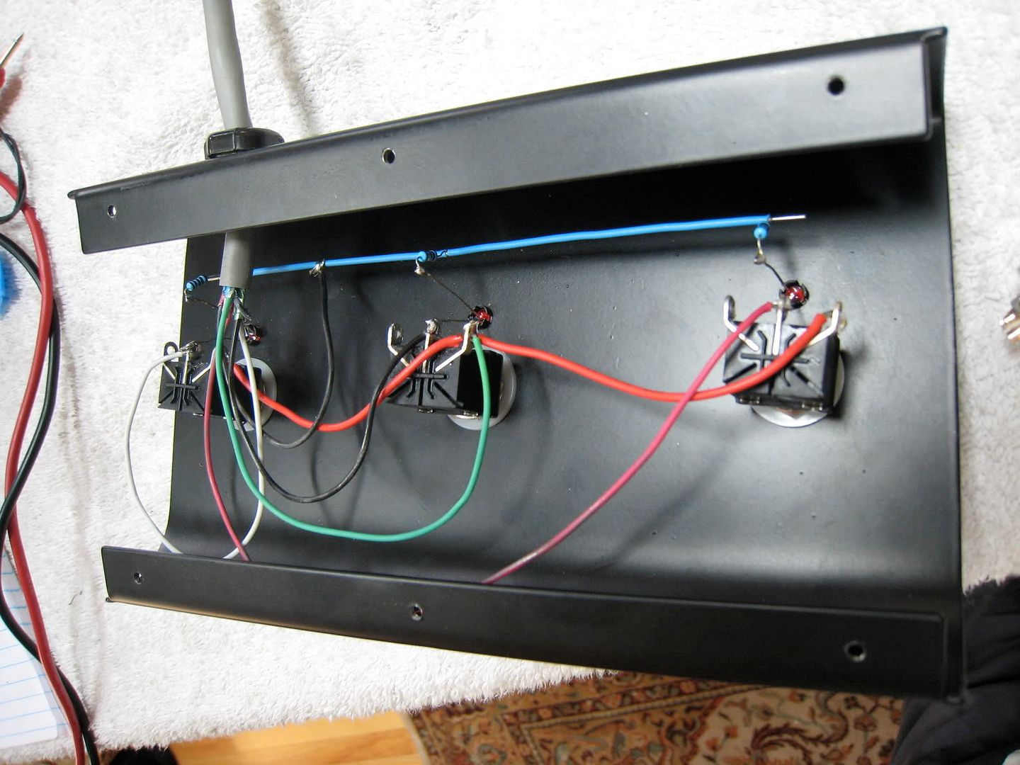
[IMG:640:480]http://i260.photobucket.com/albums/ii9/ ... G_1327.jpg[/img]
[IMG
 576]http://i260.photobucket.com/albums/ii9/ ... -deric.jpg[/img]
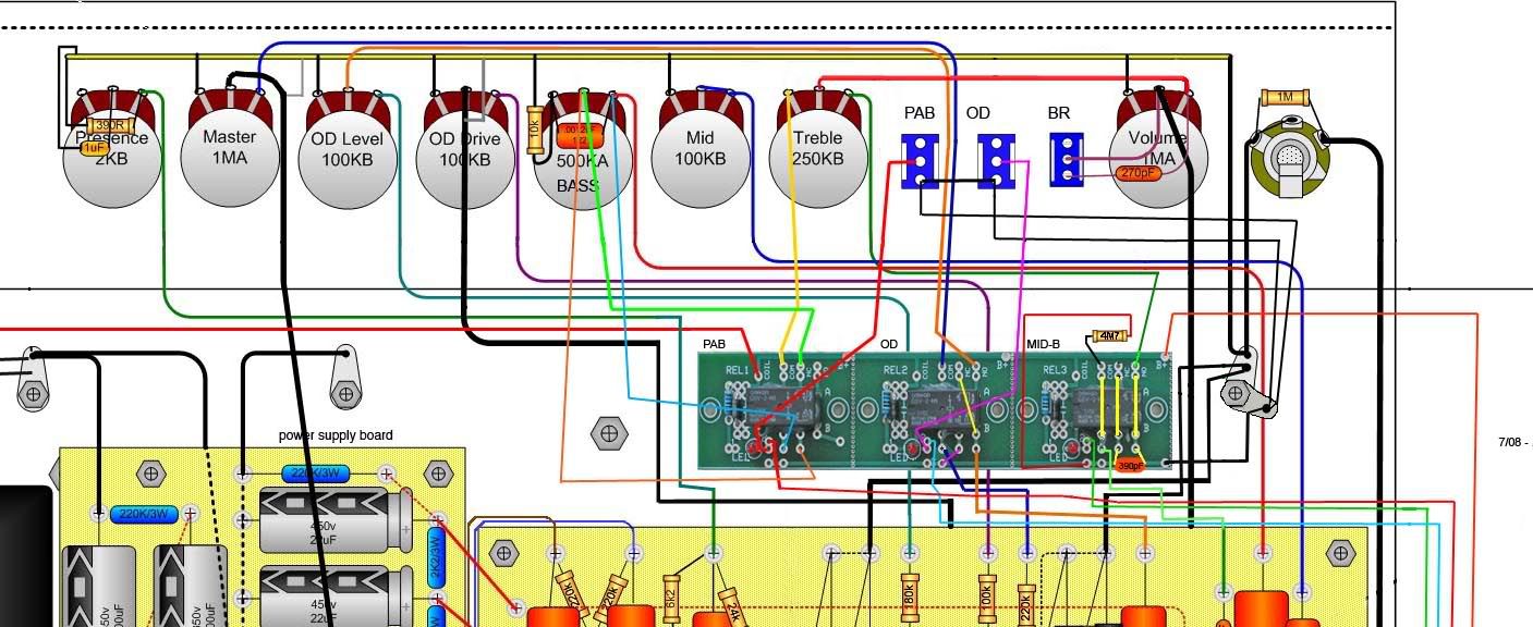
-
dcribbs1412
- Posts: 1378
- Joined: Wed Jun 11, 2008 6:56 pm
- Location: Arizona Desert
Re: footswitch problems
Thanks angelodp for the
nice detailed pics
nice detailed pics