Ryan & Erwin's SSS #002 Madness

Overdrive Special, Steel String Singer, Dumbleland, Odyssey, Winterland, etc. -
Members Only

Moderators: pompeiisneaks, Colossal

Post Reply
User avatar
rccolgan
Posts: 415
Joined: Mon Apr 03, 2017 1:39 am
Contact:

Re: Ryan & Erwin's SSS #002 Madness

Post by rccolgan »

Abe5150 wrote: Mon Jul 27, 2020 11:04 pm I thought I read that #002 had a three tube reverb is that true? And are both preamp tubes 6 and 7 part of the cathodyne phase inverter or just preamp tube 7?
Maybe they are counting the mixing tube on the mainboard (v3)?

Update on my builds: I did some additional tweaking on my personal amp and the PCB prototype based on A/B tests I was using with the Radial Engineering tube amp switcher. My original master volume pot was 830k measured and the prototype amp was 970k. I noticed a bit less top end coming through to the power section compared to the prototype so Bombacatotal/Rafael pointed to this pot as a potential culprit. I did a swap and my dead amp (by comparison) came to life with a sweeter top end with 970k and the 830k pot tamed the PCB prototype as well! Win-win! The parts selection between the two amps is very different so I can't really compare apples-to-apples, however, I was surprised by the master volume pot change. I'm always learning and this is such a fun amp to immediately hear differences.
Ryan
https://www.thetonegeek.com/
Richard1001
Posts: 254
Joined: Tue Oct 23, 2007 6:12 pm

Re: Ryan & Erwin's SSS #002 Madness

Post by Richard1001 »

Hi Ryan and Erwin,

I finished mij build today and the amp is working great. I put in relay's for the preampboost, the fet and midboost. Next to great clean tones the amp has awesome overdrive too and this can be shaped very nicely by the filters. I used 10nF caps on the filter and to the level pot (you call them cx1 and cx2 i believe in youre layout) but did use a 5uF decoupling cap on v2a. For me this provides lots of low end. I think the cap should be 5uF since the cutoff (-3db) point of a 1uF cap would be 106Hz. That is around the frequency of the low A string. (The lower the freqency's, there will be less decoupling of the cathode resistor meaning this low frequency's wil find more negative feedback over the cathode resistor and thus will not be amplified as much as mid and high frequency's.)

While the amp is working great, i did find one problem. I wondered if you ever measured the voltage on the powercaps behind the standbyswitch with the amp on standby. I did and noticed that the CF is loading the caps with a negative voltage. If you put the amp on while on standby, the filtercaps after the standbyswitch will be charged negative as soon as V7 is warmed up. This actualy makes perfect sense:

For V7 the ground is positive to the kathode witch is at a negative voltage. It doen't matter if you put negative 200 volts on the cathode and zero on the anode or zero at the cathode and positive 200 volts on the anode. Either way, the tube is seeing 200 volts. When the amp is in standby the voltage on the caps behind the switch drops to zero, but even at 0 volt will still be positive to the cathode's of V7. This tube will therefore keep conducting current and charges the caps negavive!

I think a solution would be a reversed diode on the filtercap for the screens to ground. This way the current will flow to ground and will not charge the caps negative in standby. Another benefit is that the voltage on the cathode's of V7 will stay within theire normal range and will not drop below the maximum cathode to heater voltage. It will stay around -70 volts in standby.

Another thing i tryed with succes and might be interesting is lowering the B+ voltage on V7 with a zenerdiode in series. I used a 120 Volt 1,3 watt zener in the supply from screenvoltage to the tube. This lowers the B+ voltage on V7 by 120 volt, regardless of the current the tube draws. So the B+ voltage will remain stable, regardless of the current draw of V7. Now this is not the intended use of a zenerdiode, but maybe could be something Dumble did. A zenerdiode is very small and could be wired under the board directly to the tube. The board would measure a high voltage, but on the socket itself it would be lower...

I guess we will never know for sure.
User avatar
erwin_ve
Posts: 1732
Joined: Fri Jan 25, 2008 8:06 am
Location: Dordrecht, Netherlands
Contact:

Re: Ryan & Erwin's SSS #002 Madness

Post by erwin_ve »

Hi Richard,

Great to hear your amp is working!
You added some nice features and protective zeners.
Now we want to see pics!

Erwin
User avatar
martin manning
Posts: 13430
Joined: Sun Jul 06, 2008 12:43 am
Location: 39°06' N 84°30' W

Re: Ryan & Erwin's SSS #002 Madness

Post by martin manning »

Interesting observation on the negatively charged screen caps on standby. Is there a complete schematic for this project somewhere? I have the one from Ryan's Github, but it seems to be missing a few things.
User avatar
M Fowler
Posts: 14019
Joined: Wed Jan 16, 2008 2:19 am
Location: Walcott ND

Re: Ryan & Erwin's SSS #002 Madness

Post by M Fowler »

I think the mounting hardware is MK1000 10-32" from Aircraft Spruce & Specialty Co.

I made a mistake and ordered the K1000 10-32 which I knew was the wrong units but I did it and will use them somewhere else.

Well interesting that neither one of these fit the chassis?

Mark
Last edited by M Fowler on Tue Sep 01, 2020 6:06 pm, edited 1 time in total.
Richard1001
Posts: 254
Joined: Tue Oct 23, 2007 6:12 pm

Re: Ryan & Erwin's SSS #002 Madness

Post by Richard1001 »

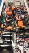
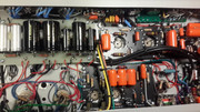
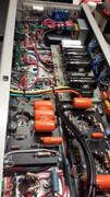
Here are some pictures Erwin...

Image

Image

Image

Image

Image
User avatar
rccolgan
Posts: 415
Joined: Mon Apr 03, 2017 1:39 am
Contact:

Re: Ryan & Erwin's SSS #002 Madness

Post by rccolgan »

Congrats, Richard!

Erwin and a few have been helping with the schematic fixes. I'm pretty confident about it and happy to adjust if anyone finds a problem. https://github.com/colganr/LTSpiceCircu ... Export.pdf

As for the reverse 7v charging... I have not looked for it specifically however that's concerning! Do we think it's from the standby switch? or something else? New territory for me...
Ryan
https://www.thetonegeek.com/
User avatar
martin manning
Posts: 13430
Joined: Sun Jul 06, 2008 12:43 am
Location: 39°06' N 84°30' W

Re: Ryan & Erwin's SSS #002 Madness

Post by martin manning »

rccolgan wrote: Thu Aug 27, 2020 9:53 pm Erwin and a few have been helping with the schematic fixes. I'm pretty confident about it and happy to adjust if anyone finds a problem. https://github.com/colganr/LTSpiceCircu ... Export.pdf

As for the reverse 7v charging... I have not looked for it specifically however that's concerning! Do we think it's from the standby switch? or something else? New territory for me...
Thanks Ryan, I believe that's the same as the one I have. It's missing the reservoir cap, the bias circuit is incomplete (not connected to the HT with a rectifier), the FET node is not connected to the power rail, and there is no FET circuit.

The negative charge on the screen cap is there because the CF driver cathodes are connected to the negative bias (which comes on with the main power), and the anodes are connected to ground through the power supply rail and the FET voltage divider, which is acting like an anode resistor. The other filters will see negative voltages too. A few seconds is probably not going to bother an aluminum electrolytic much, but it might if it were left that way for some time. Richard's fix sounds like it will work fine.
Richard1001
Posts: 254
Joined: Tue Oct 23, 2007 6:12 pm

Re: Ryan & Erwin's SSS #002 Madness

Post by Richard1001 »

rccolgan wrote: Thu Aug 27, 2020 9:53 pm Congrats, Richard!

Erwin and a few have been helping with the schematic fixes. I'm pretty confident about it and happy to adjust if anyone finds a problem. https://github.com/colganr/LTSpiceCircu ... Export.pdf

As for the reverse 7v charging... I have not looked for it specifically however that's concerning! Do we think it's from the standby switch? or something else? New territory for me...
Thanks!

No it is not the standby switch. Putting the amp on standby shuts off the voltage on the caps behind the switch (like its supose to)
Without the positive supply feeding the caps the voltage normaly would drop to zero. In this case V7 will keep working because it has a negative cathode supply that does not shut off. The negative supply voltage is around 400 volt and for both cathodes is divided over the 220K cathode resistors and two 470k resistors in parralel. This leaves around minus 200 volt. Since it is a cathode folower the cathode wants to go to the same potential as the grid. The grid is fed by a voltage divider (820k/130k) on a fixed voltage higher than - 200 volt and the cathode wants to follow this. (Like it does providing the bias voltage) With minus 200 volt on the kathode and zero volt on the caps, a current will flow from negative to positive (- 200 to 0). (For the tube 0 volt on the anodes is a positive anode supply to the cathode. All tha matters is the potential diffrence) This current will find its way to ground trough (for instanse) the 270k resistors on the 100uF caps. A current trough a resistor results in a potential diffrence (voltage). Without the stronger powersupply keeping the caps charged positive, the current flow in V7 will pull the caps below zero. (All the caps behind the standbyswitch)

Now electrolytic caps can take a little negative voltage, but i measured - 20 volts on the caps before i saw it and shut off the power. Allthough there is very little current, it doesn't seem healthy for the caps in my opinion.
Richard1001
Posts: 254
Joined: Tue Oct 23, 2007 6:12 pm

Re: Ryan & Erwin's SSS #002 Madness

Post by Richard1001 »

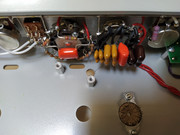
Here some pictures of the filter switches. By coincidence i ordered CTS 11 position switches and i like how everything can be fitted on the switch. Also a picture of the PAB and midboost. They are mounted under the pots and switches to save space. (Thanks for the relay board Erwin) The other board i got from Nik from Ceriatone. I used this for the midboost and mounted it upside down under the mid pot. (The fet relay is on the fet board.) The footswittch will have 3 switches and 3 leds.
I wired it so that without footswitch everything works as the amp would without relays.

I am very exited about the amp and the amazing sound it has. To Erwin and Ryan i want to say thanks for all the great work you put in to this project!

Image

Image

Image
User avatar
rccolgan
Posts: 415
Joined: Mon Apr 03, 2017 1:39 am
Contact:

Re: Ryan & Erwin's SSS #002 Madness

Post by rccolgan »

martin manning wrote: Thu Aug 27, 2020 10:33 pm
rccolgan wrote: Thu Aug 27, 2020 9:53 pm Erwin and a few have been helping with the schematic fixes. I'm pretty confident about it and happy to adjust if anyone finds a problem. https://github.com/colganr/LTSpiceCircu ... Export.pdf

As for the reverse 7v charging... I have not looked for it specifically however that's concerning! Do we think it's from the standby switch? or something else? New territory for me...
Thanks Ryan, I believe that's the same as the one I have. It's missing the reservoir cap, the bias circuit is incomplete (not connected to the HT with a rectifier), the FET node is not connected to the power rail, and there is no FET circuit.
Ah yes. I focused on getting the simulation and voltages to work on the signal and deprioritized the power section accuracy in the moment. I'm happy to merge your updates into GitHub if you have a local copy or I'll update myself in the next cycle.
Richard1001 wrote: Thu Aug 27, 2020 10:42 pm
rccolgan wrote: Thu Aug 27, 2020 9:53 pm Congrats, Richard!

Erwin and a few have been helping with the schematic fixes. I'm pretty confident about it and happy to adjust if anyone finds a problem. https://github.com/colganr/LTSpiceCircu ... Export.pdf

As for the reverse 7v charging... I have not looked for it specifically however that's concerning! Do we think it's from the standby switch? or something else? New territory for me...
Thanks!

No it is not the standby switch. Putting the amp on standby shuts off the voltage on the caps behind the switch (like its supose to)
Without the positive supply feeding the caps the voltage normaly would drop to zero. In this case V7 will keep working because it has a negative cathode supply that does not shut off. The negative supply voltage is around 400 volt and for both cathodes is divided over the 220K cathode resistors and two 470k resistors in parralel. This leaves around minus 200 volt. Since it is a cathode folower the cathode wants to go to the same potential as the grid. The grid is fed by a voltage divider (820k/130k) on a fixed voltage higher than - 200 volt and the cathode wants to follow this. (Like it does providing the bias voltage) With minus 200 volt on the kathode and zero volt on the caps, a current will flow from negative to positive (- 200 to 0). (For the tube 0 volt on the anodes is a positive anode supply to the cathode. All tha matters is the potential diffrence) This current will find its way to ground trough (for instanse) the 270k resistors on the 100uF caps. A current trough a resistor results in a potential diffrence (voltage). Without the stronger powersupply keeping the caps charged positive, the current flow in V7 will pull the caps below zero. (All the caps behind the standbyswitch)

Now electrolytic caps can take a little negative voltage, but i measured - 20 volts on the caps before i saw it and shut off the power. Allthough there is very little current, it doesn't seem healthy for the caps in my opinion.
Thank you for explaining, Richard (and Erwin via Skype). This is extremely helpful and I see the how the diode is helpful for the health of the caps. I have a few questions that will be helpful to me and others reading if you don't mind. I will also update my layout with these suggestions as it seems pretty important.
  • For the Zener diode, maybe my eyes are playing tricks but is this possibly a zener between the board and the socket in the attached picture? (or is this a good idea potentially?)
  • Any concerns with the affect of "tone" implementing the zener because of the lower voltage?
  • Any concerns or observation with radiation noise coming from the zener & reverse voltage protection diode?
You do not have the required permissions to view the files attached to this post.
Ryan
https://www.thetonegeek.com/
Richard1001
Posts: 254
Joined: Tue Oct 23, 2007 6:12 pm

Re: Ryan & Erwin's SSS #002 Madness

Post by Richard1001 »

For the zenerdiode you selected: Going for a 5 watt zener is a bit over the top. It will probably work, but a zener needs to be at a correct bias. For it to work correctly there needs to be a minimum amount of current trough the zener. If you calculate the current trough the tube you will find 1,3 mA anode current for one half of the tube. Times two anodes makes 2,6 mA. The current a zener can handle is easy to calculate, just divide the power rating by the voltage rating. In my case 1,3/120 = 10,8 mA. This is 4 times what you need and the zener has enough current to function correct.

As for noise, there is none. I could not detect any extra noise from the zener. The reverse diode doen't make noise and can't produce noise since it is tied to ground on both sides. (The B+ beeing AC ground trough the filtercap).

The reverse diode i would consider a necessity. You could put this on the filtercap board over the cap for the screen voltage. I would have done this myself if i would have known the need for it in advance.

The zener is optional. I can hear a sound diffrence, but only in the very low frequency's. There is either more bass or it is more loose on a lower voltage. This makes sense i guess because V7 in the middle of the negative feedback loop (negative feedback from the speakeroutput on V6 and the powertubes). The lower voltage on V7 wil change this loop and the speakerdampening somewhat. Also the grid voltage on the powertubes is 1 volt lower (-47) on the lower voltage than on the high voltage (-46).

On the other hand there could be to much worry over the high voltage on V7. I have been looking further and have found in older datasheets that the Va0 max = 550 volt for a 12ax7. This is the maximum anode voltage with zero platecurrent. The 300V max rating is (i guess) at max anode dissipation. Since both plates stay way below the max dissipation, maby the voltage is no issue at all. I did some temperature measurements with an inrared meter and here was only 3 degrees (celcius) diffrence between V7 and V6. So chances are there is nothing to worry about in regard to the higher volage on V7. I don't know myself if i will leave the zener in or not . I used a huge output transformer ( http://www.classictone.net/40-18072.html) and allready have a lot of low end. The reverse diode stays fur sure.
User avatar
martin manning
Posts: 13430
Joined: Sun Jul 06, 2008 12:43 am
Location: 39°06' N 84°30' W

Re: Ryan & Erwin's SSS #002 Madness

Post by martin manning »

Looks like a resistor in that picture to me. I wouldn't anticipate any noise from adding the diodes. A 1N4007 across the screen cap with anode to ground should be fine for the negative voltage drain, and the Zener you linked will work. The bipolar supply running off the 60V bias tap I proposed does not have either of these issues, but requires a few more parts.
Richard1001
Posts: 254
Joined: Tue Oct 23, 2007 6:12 pm

Re: Ryan & Erwin's SSS #002 Madness

Post by Richard1001 »

It is a solid way to lower the B+ on V7 Martin, but In my opinion a change in the applied anode voltage will result in a different perfomance of the tube and therefore will have some influence on the sound of the amplifier. (either good or bad) I think the transconductance and internal resistance of the tube changes. (according to the application notes)

I found a schematic of the McIntosh 240 amplifier. It has a 12ax7 CF driving the 6l6 tubes. The plate voltage of the 12ax7 is taken from the screens of the 6l6 tubes and is 430 volts. The cathode voltage is minus 45 volts. For me this confirms it is possible to have a 12ax7 working on a higher voltage than 300 volts. I will delete the zener in my amp and just keep the high voltage on the tube.

Here is the schematic of the McIntosh amplifier:

Image
Bombacaototal
Posts: 1675
Joined: Thu Oct 06, 2016 5:53 am

Re: Ryan & Erwin's SSS #002 Madness

Post by Bombacaototal »

Richard, the McIntosh schematic you linked is where the Odyssey amps came from, it is not a CF (cathode follower, ie the signal is taken from the cathode of the second tube) as most SSS amps (which come from SVT), but it is a “plate follower”(ie the signal is taken from the plate of the second tube), basically AC vs DC. Also tube compliment on these amps is different, the second PI tube is actually a 12BH7 and will see a bit over 300V on plates, and the tube will get extremely hot
Last edited by Bombacaototal on Sat Aug 29, 2020 7:01 am, edited 1 time in total.
Post Reply