In the .pdf's below are all-eyelet versions of the ODS PCB's and preamp eyelet board that TAG member JBorders had made up, with some variations and additions. The dimensions and mounting centers from the original boards have become the "TAG standard" to which other members have had board sets and chassis fabricated for sale. They were not designed to match any particular Dumble ODS, and there are some differences with respect to the layout drawings posted by Tony Albany. The original intent of the eyelet board drawings was to provide a DIY replacement for the JBorders PCB and Preamp board set, with the same overall dimensions and mounting centers. The schematic below is a marked up version of the icracer schematic drawn from #124 photos, with changes typical of amps built using these eyelet board layouts and TAG standard chassis.
Notes:
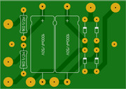
All of the high voltage power supply filters are located on the main filter board, which eliminates the need for the remotely-mounted B+4 and B+5 filter capacitors seen in some layouts.
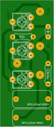
The bias supply/main rectifier board has two bias supply filters and four HV rectifiers, as seen in the later SN amps. Refer to the #183 layout drawing for details of the connections to the bias trimmer pot and B+.
An alternate “fail-safe” bias supply has been included, along with its revised bias pot connections. This circuit uses the same eyelet board pattern as the original, but in the event of a bias pot failure it will deliver the lowest available voltage rather than letting it float.
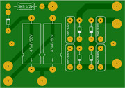
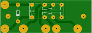
The relay power supply board can be configured with either a FW doubler or a FWB rectifier to operate from 6.3 or 12.6 VAC input respectively.
The preamp board layout closely matches Dumble's ODS component layout (4th Gen), so any important interactions should be preserved. Lowest circuit impedance to AC ground is shown by a vertical line "|" on the film capacitors. Orienting the outer foil lead in that direction is recommended, but it is not known if that convention was followed in original amps.
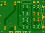
The FET board layout required some rework for eyelet construction within the same dimensions as the PCB, but it has been proven to work well.
OD relay connections for all variants are shown for OD "on" when the OD relay coil is energized. Some original amps were configured in the opposite way.
A FET boost relay schematic and layout has been included for a foot-switched boost with a manual pull-on and gain control on the front panel. More discussion on the foot switched boost is located here: https://ampgarage.com/forum/viewtopic.p ... 22#p384122
Also included is an eyelet board layout for an alternate bipolar power supply for the SSS post-PI CF driver tube using the standard 60VAC bias tap.
You do not have the required permissions to view the files attached to this post.
Last edited by martin manning on Fri May 09, 2025 1:17 pm, edited 67 times in total.