Mojotone JTM45 Schematic in Emailable Form?
Moderators: pompeiisneaks, Colossal
-
steven21042
- Posts: 23
- Joined: Thu Jul 21, 2011 3:50 pm
- Location: South Florida
Re: Mojotone JTM45 Schematic in Emailable Form?
So, in terms of tonal additiive the 5AR4/GZ34 will add what?....more chime, more mid scoop, more thump, more of the GOOD WOOD BOX tone? Or, does the tube simply enable the 34s to ROCK in the 45 circuit? ..or...none of these? 
Everything Happens the way it's Supposed to.
-
steven21042
- Posts: 23
- Joined: Thu Jul 21, 2011 3:50 pm
- Location: South Florida
Re: Mojotone JTM45 Schematic in Emailable Form?
I'm thinking I should RE-DO the heater wiring. Will it be a lot of trouble? Any suggestions, comments..??
You do not have the required permissions to view the files attached to this post.
Everything Happens the way it's Supposed to.
-
The New Steve H

- Posts: 1047
- Joined: Mon May 30, 2011 11:24 pm
Re: Mojotone JTM45 Schematic in Emailable Form?
Steve asked me about this, and it seemed like he might be well-advised to tighten up the loops in the heater wiring.
Relax. It's SUPPOSED to smoke a little.

Re: Mojotone JTM45 Schematic in Emailable Form?
This is something that is troublesome to fix after the amp is built. If there is any doubt, rework it. Heaters are "funny" in that sometimes they are just fine for no rhyme or reason, and other times, you mess up just a little bit and you're sorry. I think the most important thing about heater wiring is to keep it clear of the signal wiring. There are many schools of thought on how best to do this and all of them seem to work.
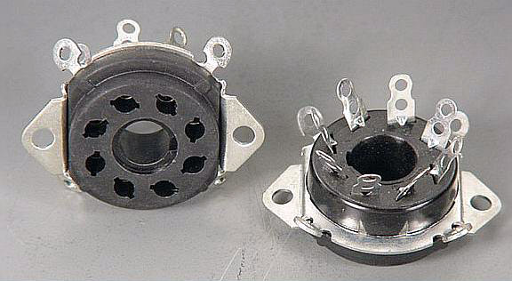
Good reading here, but not the picture I'm thinking about. http://www.apexjr.com/images/8PINOCTAL4.jpg
You can always try doing it Hiwatt style http://www.performing-musician.com/pm/j ... ternal.jpg
Gabby does a nice job of showing how: http://www.youtube.com/watch?v=ZxFBid3r8aM and especially for the 12AX7 here: http://www.youtube.com/watch?v=rFghwLDOPsA&NR=1 notice how tight he wraps the brown wire to the socket.

Re: Mojotone JTM45 Schematic in Emailable Form?
Steven, whoever laid out that board for an JTM45 circuit hosed it up. No wonder you were having troubles with the layout. There are turrets where there shouldn't be and there's even one missing.steven21042 wrote:I'm thinking I should RE-DO the heater wiring. Will it be a lot of trouble? Any suggestions, comments..??
Nevertheless, you need to add a 16uf cap to the board or else the preamp won't have any filtering. I might not be pretty but you could connect the positive end of the 16uf cap to the 10K and then connect the negative tail to ground. I would hide it under the board(it would be cleaner) if it was me, it might not look correct, but you would have all the correct functionality.
Also, I assume your bias pot is setup to mount between the 47K and the bare strand that terminates to that 15K resistor in the bias circuit.
TM
Re: Mojotone JTM45 Schematic in Emailable Form?
The rectifier tube's job is converting AC to DC. Same purpose as diode rectifiers. No audio signal passes through it.steven21042 wrote:So, in terms of tonal additiive the 5AR4/GZ34 will add what?....more chime, more mid scoop, more thump, more of the GOOD WOOD BOX tone? Or, does the tube simply enable the 34s to ROCK in the 45 circuit? ..or...none of these?
It doesn't affect tone as much as "feel" or touch response. Tube rectifiers can "sag" or "give" a little when hitting chords at loud volumes. This gives a slightly compressed sound and can feel smoother than solid-state rectifiers. GZ34's do this a little bit but it's more noticeable in low watt amps like Marshall 18w with an EZ81 tube.
-
steven21042
- Posts: 23
- Joined: Thu Jul 21, 2011 3:50 pm
- Location: South Florida
JTM48.....
Merc, I couldn't begin to think about where to put in a 16UF cap. I'm not sure I even know what one is. EL34s , KT66s, tube rectified or not, JTM45 or JTM50, missing turrets then not enough of them. I wanted a Metro with instructions then I was told that this one was a Metro 45 . Then I find out it's not. I want desperately to build this thing but everything it seems is against me.
Everything Happens the way it's Supposed to.
Re: Mojotone JTM45 Schematic in Emailable Form?
Steven, don't give up hope. Inexperienced builders experience a certain amount of frustration. It's normal. We all started there. In your case, you've got a project I would rate as "medium" for complexity. This means a lots of parts, but a tested circuit. Your snafu with having the wrong board or an incorrectly made board (whatever) is just one of those challenges that you will need to push through. You can do it. I helps to have experience -- that's what we are here for. What you need most is patience. Frustration promotes a lack of patience so you might be working overtime to keep it in check.
If this project goes slower than you expect, are there really any meaningful consequences? I am guessing no. It is a time to learn to enjoy the building and problem solving experience. When you focus on the journey rather than the end, you'll enjoy it more. I can only speak for myself, but I tend to have a bit of disappointment when I finish an amp. It's nearly always bittersweet because I'm terminating a project and having the project to do is part of the fun of it. I am suggesting a shift in outlook will help.
Now that a glitch has been identified, focus on how to overcome it without wrecking the project. It can be done. If it were me, I'd take a serious step back at this point. I'd go over the schematic and compare it to the build. I'd do it twice. Once from left to right and once from right to left. Make two copies of the schematic and mark it up with a yellow highlighter or maybe use several colors and take notes. You'd be surprised at the benefit you get from doing that. It's similar to an old-school drawing technique - if you can't get it looking real, turn the object upside down and the draw it - it frees the mind from certain suppositions.
Once you identify the problems post what you find. I think you will receive suggestions on effective ways to deal with them. This is where on line forums are really at their best.
You can do it and you'll be very pleased with the result.
Meanwhile, I'll look at that cap problem too -- group think... maybe I'll see a way out.
Re: Mojotone JTM45 Schematic in Emailable Form?
I missed it before. I think Tonemerc gave you the cap solution. if you aren't clear about what he means, maybe someone will copy your picture and draw it in there to show you. I am very slow at deciphering a build making me not the best candidate to do it.
Re: Mojotone JTM45 Schematic in Emailable Form?
Here's a quick drawing that shows how to connect the missing cap. You should be able to fit one under the board and solder the positive lead (red in the image) to the bottom of the turret so it won't be visible.
It will be an electrolytic cap that looks similar to the two black caps on the left end of your board, except larger.
It will be an electrolytic cap that looks similar to the two black caps on the left end of your board, except larger.
You do not have the required permissions to view the files attached to this post.
Re: Mojotone JTM45 Schematic in Emailable Form?
Thanks Plexiplexitone wrote:Here's a quick drawing that shows how to connect the missing cap. You should be able to fit one under the board and solder the positive lead (red in the image) to the bottom of the turret so it won't be visible.
It will be an electrolytic cap that looks similar to the two black caps on the left end of your board, except larger.
Steven, that's how you would electrically connect that cap as I mentioned. Now the trick is to mount it. So to mount the cap hidden under the board, the board mounting standoffs will need to be tall enough to clear the height of the cap and I would be surprised if 3/4" standoffs were included in those parts. Therefore, if you can't mount it under the board, options are across the top or maybe parallel to the main board in the front.
TM
-
steven21042
- Posts: 23
- Joined: Thu Jul 21, 2011 3:50 pm
- Location: South Florida
JTM48
I populated my board just (I think) just like this board (located on post # 20 this page) which is from a Mojo JTM45 kit like mine. I'm trying to follow this build's instructions but like I said earlier the instructions given are for the experienced builder. It seems that the "Kindness" build shown here and the "Guttermouth" build were built according to the supplied layout and schematic. I know very little about schematics and layouts so..there you have it.....hosed.

Everything Happens the way it's Supposed to.
-
The New Steve H
- Posts: 1047
- Joined: Mon May 30, 2011 11:24 pm
Re: Mojotone JTM45 Schematic in Emailable Form?
If all else fails, I can drive up there and turn it into a 50-watt Herzog.
Relax. It's SUPPOSED to smoke a little.
Re: Mojotone JTM45 Schematic in Emailable Form?
Steven here is a good tutorial about heater wiring.
http://www.brown-note.com/heaters/
Don't get discouraged!
Good luck!
http://www.brown-note.com/heaters/
Don't get discouraged!
Good luck!
Tom
Don't let that smoke out!
Don't let that smoke out!
Re: Mojotone JTM45 Schematic in Emailable Form?
As an alternative to going under the board, you might consider using an old fashioned phenolic terminal strip. You should have enough room to mount it next to the board, orienting the cap along side the board rather than under it. Then, you are free to run the ground wire to the appropriate place. One of these http://www.tubesandmore.com/cemirror/inv/P-0201H.GIFToneMerc wrote:Thanks Plexiplexitone wrote:Here's a quick drawing that shows how to connect the missing cap. You should be able to fit one under the board and solder the positive lead (red in the image) to the bottom of the turret so it won't be visible.
It will be an electrolytic cap that looks similar to the two black caps on the left end of your board, except larger.
Steven, that's how you would electrically connect that cap as I mentioned. Now the trick is to mount it. So to mount the cap hidden under the board, the board mounting standoffs will need to be tall enough to clear the height of the cap and I would be surprised if 3/4" standoffs were included in those parts. Therefore, if you can't mount it under the board, options are across the top or maybe parallel to the main board in the front.
TM