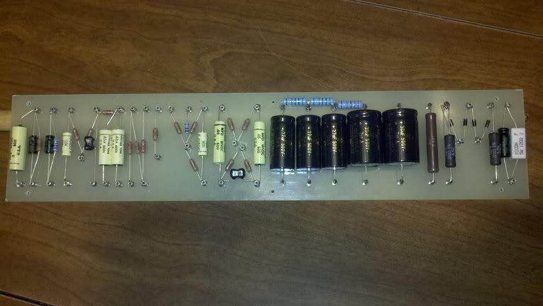
I actually started this a while back. Just ordered the transformers today. Maybe some of you guys can look at this picture and tell me if you see anything wrong. I am trying to replicate the original, older model of X10.
[IMG:766:432]http://i946.photobucket.com/albums/ad30 ... 134174.jpg[/img]
I'm stuffing this one into a vacant combo cab... AXL Akita 20. It has an Alphatone (?) 8". I'm gonna pull it out and open the hole up for a 10"... I'm thinking a Greenback 10.
If you guys think I should choose differently or know of, some good tweaks/mods please let me know. I will be pulling the trigger for the speaker and some tubes in the next few weeks so any suggestions would be much appreciated.
BTW... thanks to all the guys who went over this circuit before. I hope I can get some of those great tones as seen in the Greg V video!
Below I posted an internet pic of the combo...
Tony
EDIT: I don't know why this ended up in the Trainwreck discussion... will one of the mods please move it to the Tech Discussion section?
Another X10 Build
Moderators: pompeiisneaks, Colossal
-
dorrisant

- Posts: 2769
- Joined: Tue Sep 21, 2010 1:27 pm
- Location: Somewhere between a river and a cornfield
- Contact:
Another X10 Build
You do not have the required permissions to view the files attached to this post.
"Education is what you're left with after you have forgotten what you have learned" - Enzo

Re: Another X10 Build
looking great. Definitely report back once you get it fired up.
I Hate being bi-polar; It's awesome!

Re: Another X10 Build
Hi Dorrisant,
just wonder about the directions of your PI anodes. Are you shure the mica is at the PI anodes? Isn´t it the 2 bias Rs where you put the mica instead to the opposit. It looks like you have the mica at the 2x220k instead of 100k/82k (anode). If you look to the preamp anodes- they are upward, like the PI anodes should do. The bias downward. Or is it no mistake but planed?
Compare it with a TW layout. Upward are the tubes, downward the pots usually. You have the PI grids up but the anodes down? The balanceing mica cap should be between the anodes, not the bias Rs.
Best
Hans-Jörg
-
dorrisant
- Posts: 2769
- Joined: Tue Sep 21, 2010 1:27 pm
- Location: Somewhere between a river and a cornfield
- Contact:
Re: Another X10 Build
Hans-Jörg,
Good eyes! This was intentional. I made this layout while looking at pictures of the original amp. They have since been removed from the site they were on. I am sure that the fizz cap was on the power tube side of the coupling caps though. I don't know what difference it will make but I will find out soon enough. Maybe some of the other guys would like to elaborate on the difference.
Thanks for looking.
I do see that the power tube Rk needs to be changed from 5w to 10w...
Tony
"Education is what you're left with after you have forgotten what you have learned" - Enzo

Re: Another X10 Build
That is definitely correct. The fizz cap is located across the fixed pair of 220k/220k grid leak resistors, after the PI output coupling caps.dorrisant wrote:I am sure that the fizz cap was on the power tube side of the coupling caps though.
Re: Another X10 Build
I concur about the PI treble cap. Also perhaps it is in the TW section because this amp is very similar to a Liverpool...

Re: Another X10 Build
Moved as requested
Looks nice. I have not heard of an "x10". Looks interesting. Any clips I can listen to?
Looks nice. I have not heard of an "x10". Looks interesting. Any clips I can listen to?
-
dorrisant
- Posts: 2769
- Joined: Tue Sep 21, 2010 1:27 pm
- Location: Somewhere between a river and a cornfield
- Contact:
Re: Another X10 Build
Thanks for the relocation...
Here is the Greg V demo video:
http://www.youtube.com/watch?v=KGpIRj6MZTM
I have a few guys ready to do some demos as soon as I get it done. I will post them as soon as possible.
Tony
Here is the Greg V demo video:
http://www.youtube.com/watch?v=KGpIRj6MZTM
I have a few guys ready to do some demos as soon as I get it done. I will post them as soon as possible.
Tony
"Education is what you're left with after you have forgotten what you have learned" - Enzo
Re: Another X10 Build
a schematic would be nice, hint hint 
Re: Another X10 Build
The AmpGarage helps those who help themselvesfullwood wrote:a schematic would be nice, hint hint
http://ampgarage.com/forum/viewtopic.ph ... t=xits+x10
Re: Another X10 Build
Many thanks Colossal, thats a great thread, thinking of building one of these using ecl86's in the power section just for giggles.Colossal wrote:The AmpGarage helps those who help themselvesfullwood wrote:a schematic would be nice, hint hint
http://ampgarage.com/forum/viewtopic.ph ... t=xits+x10
Re: Another X10 Build
It's a long and arduous read with Surfsup bearing the brunt of the pain as he built one. Good luck with your build!fullwood wrote:Many thanks Colossal, thats a great thread, thinking of building one of these using ecl86's in the power section just for giggles.
-
dorrisant
- Posts: 2769
- Joined: Tue Sep 21, 2010 1:27 pm
- Location: Somewhere between a river and a cornfield
- Contact:
Re: Another X10 Build
Well worth the effort!Colossal wrote:It's a long and arduous read with Surfsup bearing the brunt of the pain as he built one. Good luck with your build!
Tony
"Education is what you're left with after you have forgotten what you have learned" - Enzo
-
dorrisant
- Posts: 2769
- Joined: Tue Sep 21, 2010 1:27 pm
- Location: Somewhere between a river and a cornfield
- Contact:
Re: Another X10 Build
Ok... progress.
Went through the light bulb limiter startup. Blew the fuse and the neon bulb without the limiter. Forgot to put a dropping resistor in there for it (saw that the bulb is only rated up to 110v). Switched the wiring to the filament supply since I had plenty of 6v bulbs. Went back through it and fired it up again...
Bingo! We have life.
Sounds like 60 cycle hum needs to be addressed (or redressed). I had to run the 120v where I didn't want to.
New speaker -10" Greenback (made in UK) sounds ratty for now. I bet it will sing before too long.
Too late to rip anymore tonight, but I was hearing a wide variety of tones with two different guitars... sounding pretty good for a newborn!
More later;)
Need to finish the faceplate... not my favorite part.
Went through the light bulb limiter startup. Blew the fuse and the neon bulb without the limiter. Forgot to put a dropping resistor in there for it (saw that the bulb is only rated up to 110v). Switched the wiring to the filament supply since I had plenty of 6v bulbs. Went back through it and fired it up again...
Bingo! We have life.
Sounds like 60 cycle hum needs to be addressed (or redressed). I had to run the 120v where I didn't want to.
New speaker -10" Greenback (made in UK) sounds ratty for now. I bet it will sing before too long.
Too late to rip anymore tonight, but I was hearing a wide variety of tones with two different guitars... sounding pretty good for a newborn!
More later;)
Need to finish the faceplate...
You do not have the required permissions to view the files attached to this post.
"Education is what you're left with after you have forgotten what you have learned" - Enzo
-
dorrisant
- Posts: 2769
- Joined: Tue Sep 21, 2010 1:27 pm
- Location: Somewhere between a river and a cornfield
- Contact:
Re: Another X10 Build
I think this one is gonna be a lesson in grounding... can't get rid of the hum
I used twisted 20ga solid for the ins and outs of the MV changed to coax to no avail. Also shielded the 120vac... I had to run it not-so-optimal. The IEC socket is closer to the input end of the amp with a twisted (and now shielded) pair running to the other end of the amp.
Resoldered almost all turret conections too.
I'm wondering if the chassis' steel composition is not good enough for a high gain circuit like this.
I really want this thing to work correctly... I have considered reworking a new panel for the back panel (aluminum) so I can relocate the 120vac that is all over the place... attatching it a-la rj's method for chassis changes mid-engineering. maybe even a new bottom panel where the turret board and tubes are mounted. I'm never gonna sell this one so a labor of love is ok. I don't really have to try to justify drastic measures.
Easiest thing first. I need to address the grounding here. Not too many notes on this build. I'm thinking of a buss type arrangement.
Maybe I just need to shield the input from the AC nearby.
Anyone have any suggestions? I realize I've painted myself into a corner... so I am open to suggestion.
Tony
I used twisted 20ga solid for the ins and outs of the MV changed to coax to no avail. Also shielded the 120vac... I had to run it not-so-optimal. The IEC socket is closer to the input end of the amp with a twisted (and now shielded) pair running to the other end of the amp.
Resoldered almost all turret conections too.
I'm wondering if the chassis' steel composition is not good enough for a high gain circuit like this.
I really want this thing to work correctly... I have considered reworking a new panel for the back panel (aluminum) so I can relocate the 120vac that is all over the place... attatching it a-la rj's method for chassis changes mid-engineering.
Easiest thing first. I need to address the grounding here. Not too many notes on this build. I'm thinking of a buss type arrangement.
Maybe I just need to shield the input from the AC nearby.
Anyone have any suggestions? I realize I've painted myself into a corner... so I am open to suggestion.
Tony
You do not have the required permissions to view the files attached to this post.
"Education is what you're left with after you have forgotten what you have learned" - Enzo