You may want to rethink this since you only have one set of tubes driving half the impedance they are used to.Mostro wrote:
What I like about this is that the output impedance doesn't change,...
Disconnecting two power valves. Will this work?
Moderators: pompeiisneaks, Colossal
Re: Disconnecting two power valves. Will this work?
Re: Disconnecting two power valves. Will this work?
Since very little current will flow through the disconnected tubes, I would assume the voltage at the cathode will be near B+. I don't think it's a problem for the tubes though. Kevin O'Connor discusses this type of power tube switching in his book "The Ultimate Tone", including various options for automating the switch (using a MOSFET), getting rid of transtion noise, etc.Mostro wrote:d95, why should the switch be able to handle full B+? Will the voltage in the cathode rise that much? Or it´s just being cautious?
Re: Disconnecting two power valves. Will this work?
Printer, that was more of an assumption/question than a certainty...printer2 wrote:You may want to rethink this since you only have one set of tubes driving half the impedance they are used to.Mostro wrote:
What I like about this is that the output impedance doesn't change,...
I´m not that sure how the whole impedance thing works here. I know there´s plate impedance, and output transformer reflected impedance (from the secondary and the speaker). To get efficient power transfer, they should be matched (the impedances). Now, if one pair of tubes is in cutoff, the plate impedance changes? Or they don´t have impedance at all? I´m confused here.
Besides all this, If the impedance changes and the load is less than ideal with two tubes out, will the only "problem" be less eficcient power transfer? Cause that could actually be good for my objective. Of course sound would change... Or will something blow up?
I guess the only way of knowing would be trying it, maybe upping the R value little by little and observing voltages.d95err wrote:Since very little current will flow through the disconnected tubes, I would assume the voltage at the cathode will be near B+. I don't think it's a problem for the tubes though. Kevin O'Connor discusses this type of power tube switching in his book "The Ultimate Tone", including various options for automating the switch (using a MOSFET), getting rid of transtion noise, etc.Mostro wrote:d95, why should the switch be able to handle full B+? Will the voltage in the cathode rise that much? Or it´s just being cautious?
That book sounds interesting...
Re: Disconnecting two power valves. Will this work?
Say for a minute the amp was Class A biased. That means it idles half way between cutoff and saturation. So would you not only need double the idle voltage to pretty much turn the tube off?d95err wrote:Since very little current will flow through the disconnected tubes, I would assume the voltage at the cathode will be near B+. I don't think it's a problem for the tubes though. Kevin O'Connor discusses this type of power tube switching in his book "The Ultimate Tone", including various options for automating the switch (using a MOSFET), getting rid of transtion noise, etc.Mostro wrote:d95, why should the switch be able to handle full B+? Will the voltage in the cathode rise that much? Or it´s just being cautious?
Re: Disconnecting two power valves. Will this work?
Mostro wrote:Printer, that was more of an assumption/question than a certainty...printer2 wrote:You may want to rethink this since you only have one set of tubes driving half the impedance they are used to.Mostro wrote:
What I like about this is that the output impedance doesn't change,...
I´m not that sure how the whole impedance thing works here. I know there´s plate impedance, and output transformer reflected impedance (from the secondary and the speaker). To get efficient power transfer, they should be matched (the impedances). Now, if one pair of tubes is in cutoff, the plate impedance changes? Or they don´t have impedance at all? I´m confused here.
Besides all this, If the impedance changes and the load is less than ideal with two tubes out, will the only "problem" be less eficcient power transfer? Cause that could actually be good for my objective. Of course sound would change... Or will something blow up?
I guess the only way of knowing would be trying it, maybe upping the R value little by little and observing voltages.d95err wrote:Since very little current will flow through the disconnected tubes, I would assume the voltage at the cathode will be near B+. I don't think it's a problem for the tubes though. Kevin O'Connor discusses this type of power tube switching in his book "The Ultimate Tone", including various options for automating the switch (using a MOSFET), getting rid of transtion noise, etc.Mostro wrote:d95, why should the switch be able to handle full B+? Will the voltage in the cathode rise that much? Or it´s just being cautious?
That book sounds interesting...
A tube is basically a voltage controlled resistor. We can bias it more on or off, allowing more or less current through it. If we want to allow little current through we cause the impedance between the cathode and the plate to be very high. With it not supplying any amplified signal to the load (the primary) the other tube has to do it all. So rather than two tubes sharing a load you now have one doing all the work and the other off in high impedance land.
Re: Disconnecting two power valves. Will this work?
I spent most of my youth in high impedance land.
What?
Re: Disconnecting two power valves. Will this work?
Ahá! I see. So the less current that goes through the tube is kind of equivalent to what a resistor would do (I mean, a higher value R would limit the current more) The EL84 datasheet quotes 38K plate resistance for one tube in class A. Is that equivalent to the impedance?printer2 wrote: A tube is basically a voltage controlled resistor. We can bias it more on or off, allowing more or less current through it. If we want to allow little current through we cause the impedance between the cathode and the plate to be very high. With it not supplying any amplified signal to the load (the primary) the other tube has to do it all. So rather than two tubes sharing a load you now have one doing all the work and the other off in high impedance land.
So, upping the impedance in one tube by allowing less current through would make the other tube more efficient in transferring the power to the transformer and try to do all the work? Or I´m getting it all wrong?
EDIT: So by biasing a tube of each pair in cutoff I´m changing the impedance of the pair and so mismatching the tubes to the transformer. What will the consequences of that be? Tubes blowing up by trying to do the work of a pair? Less than half the power transfer? Problems in the transformer? Or no serious problems at all?
EDIT 2: It´ll take some time for all this info to sink into my head. Brain overdrive!
Re: Disconnecting two power valves. Will this work?
This graph might help an aching head.Mostro wrote:Ahá! I see. So the less current that goes through the tube is kind of equivalent to what a resistor would do (I mean, a higher value R would limit the current more) The EL84 datasheet quotes 38K plate resistance for one tube in class A. Is that equivalent to the impedance?printer2 wrote: A tube is basically a voltage controlled resistor. We can bias it more on or off, allowing more or less current through it. If we want to allow little current through we cause the impedance between the cathode and the plate to be very high. With it not supplying any amplified signal to the load (the primary) the other tube has to do it all. So rather than two tubes sharing a load you now have one doing all the work and the other off in high impedance land.
So, upping the impedance in one tube by allowing less current through would make the other tube more efficient in transferring the power to the transformer and try to do all the work? Or I´m getting it all wrong?
EDIT: So by biasing a tube of each pair in cutoff I´m changing the impedance of the pair and so mismatching the tubes to the transformer. What will the consequences of that be? Tubes blowing up by trying to do the work of a pair? Less than half the power transfer? Problems in the transformer? Or no serious problems at all?
EDIT 2: It´ll take some time for all this info to sink into my head. Brain overdrive!
[img:400:408]http://www.john-a-harper.com/tubes201/f ... curves.gif[/img]
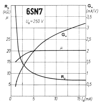
You can see as Rp goes up the current through the tube goes down. In this case the tube is a signal triode, a little simpler than a pentode and good as an example. Check out the data sheet for this tube.
http://www.wooaudio.com/docs/tube_data/6SN7.pdf
You will see the plate resistance is listed as 6700 or 7700 ohms (90V and 250V, and looking at the above curves you can see it is not one value.
Now pentodes and beam power tubes are a little more complicated than triodes and act a little differently, but ultimately you have the tube's resistance limiting how much current goes though it and it uses resistance to do it.
Now as far as the mismatched impedance running two tubes instead of four, if the amp could stand a mismatch of impedance under normal conditions, say with the four tubes and the transformer set for an 8 ohm load and you run 4 ohms, then running with a pair of tubes and a 8 ohm load will be no problem. You might also get some reduction in output because of the mismatch but I found that in my amps I got close to the same power at different impedances. I think it might be tube specific as they have different curves.
[img:600:649]http://www.r-type.org/articles/ch3-003.jpg[/img]
So how much the amp will care if it is run without an optimum load depends on the hardware , its operating point and the amp design. Now since you are trying for lower power output and using a VVR you are running the amp and output tubes more conservatively so I would think they would be less stressed than with full power supply voltage.
-
eniam rognab
- Posts: 763
- Joined: Wed May 15, 2013 4:06 am
Re: Disconnecting two power valves. Will this work?
thanks for that printer2 
im learn-ding
im learn-ding
Re: Disconnecting two power valves. Will this work?
Printer, exceptional explanation, thanks a bunch for taking the time!
More food for thought. I´ll recheck my output transformer for specs. They are made by a local winder (Argentina) that makes high quality work. Some local amp builders have compared them to Heyboers and they came out not worse or better, just different. He´s known for overbuilding things, so...
More food for thought. I´ll recheck my output transformer for specs. They are made by a local winder (Argentina) that makes high quality work. Some local amp builders have compared them to Heyboers and they came out not worse or better, just different. He´s known for overbuilding things, so...
Re: Disconnecting two power valves. Will this work?
I grounded the grids for a friends Victoria to switch between one or the other of the power tubes. It's one of those you can use two different tubes so he can go from a 6v6 to an el34 or both with the flip of a switch. He loves it.
The world is a better place just for your smile.
Re: Disconnecting two power valves. Will this work?
So Pops, that was for changing the tube in use. I assume it was a single ended parallel power tubes amp?
How would this switch interact with the active tube? Or it won´t at all? Cause with the grid grounded, there would be a path to ground trough the grid R´s of both tubes in a a pair. Let´s say they are 1K5, the total resistance to ground would be 3K. Or am I way off?
How would this switch interact with the active tube? Or it won´t at all? Cause with the grid grounded, there would be a path to ground trough the grid R´s of both tubes in a a pair. Let´s say they are 1K5, the total resistance to ground would be 3K. Or am I way off?
-
martin manning

- Posts: 13423
- Joined: Sun Jul 06, 2008 12:43 am
- Location: 39°06' N 84°30' W
Re: Disconnecting two power valves. Will this work?
Lest anyone become confused, Rp is not the resistance that controls the current through the tube as a function of grid voltage. Rp is the AC resistance at the plate (dVa/dIa) at constant grid voltage. For a 12AX7 e.g., at a given reference point (250Va-k, -2Vg-k, 1.2mA Ia) Rp is listed at 62.5k. The aparrent resistance to current flow from the plate to the cathode at that point would be 250V/1.2mA or 208.3k.printer2 wrote:A tube is basically a voltage controlled resistor. We can bias it more on or off, allowing more or less current through it. If we want to allow little current through we cause the impedance between the cathode and the plate to be very high...[snip]
This graph might help an aching head.
[img:400:408]http://www.john-a-harper.com/tubes201/f ... curves.gif[/img]
You can see as Rp goes up the current through the tube goes down. In this case the tube is a signal triode, a little simpler than a pentode and good as an example. Check out the data sheet for this tube.
http://www.wooaudio.com/docs/tube_data/6SN7.pdf
You will see the plate resistance is listed as 6700 or 7700 ohms (90V and 250V, and looking at the above curves you can see it is not one value.
Re: Disconnecting two power valves. Will this work?
My bad. Failed to mention there is the dc load lines and ac load lines that govern what happens in a gain stage. I just wanted to get across the idea that the tube's resistance can change and it is not fixed and without the change in resistance we would not be getting changes in the current and voltage through and across the tube, and in turn through and across the transformer.martin manning wrote:Lest anyone become confused, Rp is not the resistance that controls the current through the tube as a function of grid voltage. Rp is the AC resistance at the plate (dVa/dIa) at constant grid voltage. For a 12AX7 e.g., at a given reference point (250Va-k, -2Vg-k, 1.2mA Ia) Rp is listed at 62.5k. The aparrent resistance to current flow from the plate to the cathode at that point would be 250V/1.2mA or 208.3k.printer2 wrote:A tube is basically a voltage controlled resistor. We can bias it more on or off, allowing more or less current through it. If we want to allow little current through we cause the impedance between the cathode and the plate to be very high...[snip]
This graph might help an aching head.
[img:400:408]http://www.john-a-harper.com/tubes201/f ... curves.gif[/img]
You can see as Rp goes up the current through the tube goes down. In this case the tube is a signal triode, a little simpler than a pentode and good as an example. Check out the data sheet for this tube.
http://www.wooaudio.com/docs/tube_data/6SN7.pdf
You will see the plate resistance is listed as 6700 or 7700 ohms (90V and 250V, and looking at the above curves you can see it is not one value.
Re: Disconnecting two power valves. Will this work?
When you ground the grid put the switch (on/on) where it will break the signal to one tube and ground it without grounding the other. Should work fine. you don't want to ground the signal, just the grid of the tube you stopped sending signal to so it is quiet.Mostro wrote:So Pops, that was for changing the tube in use. I assume it was a single ended parallel power tubes amp?
How would this switch interact with the active tube? Or it won´t at all? Cause with the grid grounded, there would be a path to ground trough the grid R´s of both tubes in a a pair. Let´s say they are 1K5, the total resistance to ground would be 3K. Or am I way off?
The world is a better place just for your smile.