weirdo tubes amp
Moderators: pompeiisneaks, Colossal
-
VacuumVoodoo

- Posts: 924
- Joined: Fri Feb 17, 2006 6:27 pm
- Location: Goteborg, Sweden
- Contact:
Re: weirdo tubes amp
How about an ECF80 or 82 in the first socket. Use the triode as low gain input stage DC coupled straight to pentode split load splitter. No weird supply voltages, no extra sockets and some extra sensitivity at the input.
Aleksander Niemand
------------------------
Life's a party but you get invited only once...
affiliation:TUBEWONDER AMPS
Zagray!-review
------------------------
Life's a party but you get invited only once...
affiliation:TUBEWONDER AMPS
Zagray!-review
Re: weirdo tubes amp
That is a really good idea. You are a gentleman and a scholar.
I have a ridiculous self-imposed constraint to try and use just the tubes that boots had sent me, but on the other hand I have to add some heptodes anyways wherever there were potentiometers.
So your sensible and elegant idea vs pulling a signal from the screen grid. Maybe I could find half a triode pair from a 7F7 and have it drive the cathodyne, I'll have to review what I was planning to do with it when I get home tonight.
[EDIT - could also use an input transformer, but it has the same problem as the coupling capacitor if it shorts - bam +90v on the guitar]
[EDIT #2 - if I use an input transformer, I don't need a phase inverter, I just hook the CV to the center tap and the signal will be in opposite phase at either end of the transformer - hook the RC grids right up to those]
Re: weirdo tubes amp
The directly-coupled cathode is cool. But for $10 I can get a 15k:600 transformer, gives me 1/5 the voltage (good for input remote cutoff tubes, especially when you've got active pickups), and by using an 8k load resistor instead of the nominal 600 ohms, I reflect back 200k at the guitar. So that's usable. Not sure what the impedance change will do to the frequency response, I'm vaguely hoping it all just works.
This is the the Edcor I'm thinking for an input transformer: https://www.edcorusa.com/pcw15k-600.
The only voltage present on the output side of the transformer is the negative bias. The design spec states input maximum voltage is 20v, fine even for hot pickups. If that's also the max voltage difference I can put between the input and output windings, then I have a problem, because the bias could be potentially be below -20.
In the event of a short, the bias voltage would go to ground. I don't know the DC resistance of the transformer, but it ought to be small - the source impedance of the 7V7 should be up around 30k, so I don't think there's any dangerous voltages in that situation. The presence of the caps in the negative control voltage supply makes a mess of that calculation though, maybe I should add a resistor between the CT of the transformer and the negative control voltage.
Updated schematic attached to this post. Log in to view, if you're so inclined.
You do not have the required permissions to view the files attached to this post.
-
VacuumVoodoo
- Posts: 924
- Joined: Fri Feb 17, 2006 6:27 pm
- Location: Goteborg, Sweden
- Contact:
Re: weirdo tubes amp
I wouldn't worry about bias voltages or even B+ flash over causing input transformer isolation breakdown. An ESD pulse directly into the input from human body charged to 10kV by walking in rubber soled shoes an a dry synthetic carpet can cause some damages. Such scenario is theoretically possible.
I'd be concerned with input signal levels and input impedance since you apparently (which I haven't caught until now) intend to plug a guitar directly into it. The transformer you have chosen is a x5 step down type....used to drive a 600 Ohm line from a high impedance source.
Guitar pickups like to see high impedance load ~1M.
What you need in way of input transformer is a High-Z specialty transformer, such as used by Lehle in their more advanced pedals.
But still, I think you'll need a proper gain stage up front, transformer or not.
On the whole, your self imposed constraint of using tubes readily available to you can be both limiting and challenging to you to think harder, which in the end is a good thing. BTW have you studied so called vari-mu compressors? The ones using 6386 variable mu /remote cut-off) dual triode as gain control element.
Heptodes are interesting animals. Why not build a heptode based voltage controlled phaser/flanger ?
Aleksander Niemand
------------------------
Life's a party but you get invited only once...
affiliation:TUBEWONDER AMPS
Zagray!-review
------------------------
Life's a party but you get invited only once...
affiliation:TUBEWONDER AMPS
Zagray!-review
Re: weirdo tubes amp
The phaser is on the list, just down the line. I'll probably use some saturable core reactors I bought off ebay, from the Hammond vibratos (see http://el34world.com/Forum/index.php?topic=10681.0 for discussions some other fellows had about building the vibratos, double the circuit and a few other modifications and you can get a phaser).
The input impedance seen by the guitar ought to be 200k - it's a 15k:600 ohm transformer driving an 8k load. Or am I missing something here? Entirely possible, everything I know Professor Google taught me.
Does it do something horrible to the transformer bandwidth when you use a larger load than the transformer was specified for? Or are you very simply saying 200k just isn't enough, and 1M is the minimum to shoot for?
I've stared at the Fairchild 660 and 670 schematics for hours, and then tried to get rid of as many of their dozens of transformers as possible. My design here keeps inching closer to it. The problem with tube input stages is that I want to attenuate the signal to avoid the terrible distortion than remote cutoff tubes have, so any gain I get just means I have to add voltage dividers to get rid of it, and then chop it down even more because active pickups are way too hot to begin with.
Maybe I should just suck it up and add the -125 V supply, and stick with the cathodyne. I can do a 5:1 voltage divider at the cathodyne's grid then.
Re: weirdo tubes amp
Since there's no reply, I'll just toss out there that I'm not trying to be obstinate, I just hate not knowing why.
Anyhow, Professor Google failed to enlighten me on what would happen with putting a larger load onto an input transformer, except vague assurances that bandwidth would suffer. But then it dawned on me, I have a sine wave signal generator, AND an unassembled reamper DI box with a 10k:600 transformer.
So, science project this weekend - I'll see how flat the frequency response is w/ the signal generator (not perfect because it's impedance won't be anything like guitar pickups) thru the transformer and into an 8k load, and then build the reamper DI box with an 8k load resistor and see how tone is affected with an actual guitar.
Re: weirdo tubes amp
Anyhow more time w/ Google and I find guitar pickups having impedances up to 50k. I expect it varies wildly with frequency as well. Thus the 1M convention for input, although I expect 200k is mostly fine. Probably obvious to everyone else already.
On to the science! I had a 56.2k load resistor, which for a 10k:600 transformer gives an input impedance of 936k, and a 10k, which gives an input impedance of 167k.
I used my signal generator at various frequencies and measured the amplitude on a straight 1m load (the raw output voltage to compare to), through the transformer with a 56.2k load, and through the transformer with a 10k load.
Here's the results:
20 Hz: raw 1.64v, 56.2k=.4v, 10k=.38v
80 Hz: raw 1.65v, 56.2k=.4v, 10k=.4v
2k Hz: raw 1.55v, 56.2k=.333v, 10k=.3v
5k Hz: raw=1.45v, 56.2k=.205v, 10k=.13v
8k Hz: raw 1.43v, 56.2k=0.95v, 10k=.126v
15k: raw 1.39v, 56.2k=.032v, 10k=.03v
20k: raw 1.3v, 56.2k=.007v, 10k=.007v
I then tried playing the guitar into an amp through the transformer with the 56.2k load. Sounded fine, maybe a little flat with the higher notes but that could have been my imagination. Alligator clips and unshielded transformers make for a noisy hummy test rig.
With the signal generator, higher frequencies get progressively more chopped off the higher the load resistor, but guitar frequencies don't seem to be impacted in test results or listening results.
Now as for what I will actually build - I fired up LTspice last night (an exciting Friday night - my wife is lucky she caught a guy like me) and came up with an exotic addition to the already exotic Greinacher voltage quadrupler to produce -125v. So now I'm torn, between doing something stupid and complex with the power supply vs doing something that might lose a bit of high end with a transformer.
Oh and that cheap $4 Mercury Magnetics power transformer took a fall off a high shelf when I pulled out my signal generator. The edges of the bobbin are busted up, I can see the coils inside, and the pins are bent. I'm thinking I'll just toss it and buy another, seeing as they're only $4.
EDIT - that's only a -4.7dB loss at 5kHz with the 56.2k load, how do people feel about that? Significant enough to forget about transformer input stages, or just fix it with some eq circuits later on?
Re: weirdo tubes amp
Here's the (partial) schematic for the voltage-controlled oscillator and the modulator. The modulator operates in two modes - heptode or ring.
Two rate control voltages drive the high- and low-pass filters, and a depth control voltage is added to the automatic gain control voltage from the sidechain that provides amplitude stability for the Wein bridge.
This is all done w/ math, simulators, and data sheets and could be a lie in practice, I need to do some prototyping. Or just build it and watch it fail, which is more likely.
The oscillator should generate frequencies from .3 Hz to 17 kHz. I have my doubts about the low frequencies though.
As is typical, I only filled in the cap & resistor values I needed to do the math on the questionable parts of the circuit. I'm being lazy about the rest.
You do not have the required permissions to view the files attached to this post.
Re: weirdo tubes amp
Nobody cares about the modulator? Not particularly useful I admit. I think I'm going to try a tube-based gyrator for a bandpass filter instead, that way I'll only need one control voltage.
I also can't get much below -15v using buck converters safely (because positive supply is +21v and I've got a maximum 40v swing between the two), so I'll make the B+ supply even more exotic and add a -150v tap, and run a tube between the +150 and -150v rails as a cathodyne for the input stage to the compressor. I know I was told that a transformer input wouldn't work, but like most people I'm headstrong and have to prove why to myself... This link had a lot of happy math: http://www.dissident-audio.com/Transfos ... Manual.pdf
Anyhow, I'm in need of some more advice. Mercury Magnetics told me that the TA-110W was 3A. It's only 2 pounds though, and about the same size as other 50VA transformers, so I'm thinking their records are wrong and it's a 1A. I want 150VA, so I can power a quad of 5C50's in addition to the bazillion other tubes going on here.
Antek has a 300VA (50v at 6A and 15v at 4A) transformer - both the oddball voltages I'm looking for (50v with voltage doublers & quadruplers so I can still power the 50v heaters on the 50C5's, and 15v to rectify and supply my buck converters). BUT this thing is 7 pounds, supported with a single screw.
I wanted to mount my chassis upside down in a combo. That 7 pound weight worries me. Would a .09 thick aluminum chassis support that? Maybe if I set it in thickened epoxy in addition to the bolt?
-
Invertiguy
- Posts: 38
- Joined: Thu Feb 21, 2013 8:49 pm
- Location: Kansas
Re: weirdo tubes amp
Why not just use an isolation transformer and a dropping resistor to light the 50c5s as a pair in series? Seems like it'd definitely save you some complexity and expense. Also, if you're not absolutely dedicated to using what you have on hand tube-wise, TV horizontal sweep tubes might be worth a look for an output stage. They're cheap, beefy for their rated dissipation, great as audio finals, and certainly fit the theme of being weird tubes. There are a lot to choose from- I'd look at the 6av5, 6bq6ga, 6dq6, 6bg6, and 6bd5 to start with.Here is a great thread on all sorts of useful TV tubes, if you're interested.
Re: weirdo tubes amp
Avoiding complexity? What do those words mean? Joking aside that's a possibility but it's really not much of a reduction in complexity as I still need +20, +150, +250 and -150 DC voltages at the end of the day. A single off-the-shelf transformer source for all that is very tempting.Invertiguy wrote:Why not just use an isolation transformer and a dropping resistor to light the 50c5s as a pair in series? Seems like it'd definitely save you some complexity and expense.
I am dedicated, for the nonsensical challenge of it. I've had to compromise a bit and add heptodes for digital control, but beyond that I'm sticking with this set.Invertiguy wrote:Also, if you're not absolutely dedicated to using what you have on hand tube-wise
Re: weirdo tubes amp
So I spent the past 7 months playing Destiny on the playstation instead of doing any kind of electronics work... whoops.
Back in the basement today - I'm working on a testing rig so I can plot curves for my heptodes (and some small signal pentodes for my radio amp).
Sadly the uTracer doesn't support multiple grids, so I'm making this out of spare junk I've got laying around. I had a ton of banana jack sockets in another project that I disassembled, and I'll use my variac to power the high voltage supply through an isolation transformer. Filament voltage will be provided by an adjustable buck converter powered by a pedal wall-wart (so up to 9v filaments, fine for the tubes I've got), and grid voltage will be provided by a pair of 9v batteries.
Anyhow here's a shot of the filament supply and LEDs that indicate when the big high voltage caps discharge (they stay lit until 10v or so using constant current sources). The bright LEDs are BRIGHT even using just a 1ma current source. Hooray for science.
[img 1024]http://i234.photobucket.com/albums/ee25 ... ix2j6j.jpg[/img]
And here's all the banana jacks and so forth. It's mostly wired up now, and I'll stick some common-value resistors and capacitors across the central bunch of jacks so I can build circuits easily just using jumper cables.
[img1024]http://i234.photobucket.com/albums/ee25 ... ygw3je.jpg[/img]
Back in the basement today - I'm working on a testing rig so I can plot curves for my heptodes (and some small signal pentodes for my radio amp).
Sadly the uTracer doesn't support multiple grids, so I'm making this out of spare junk I've got laying around. I had a ton of banana jack sockets in another project that I disassembled, and I'll use my variac to power the high voltage supply through an isolation transformer. Filament voltage will be provided by an adjustable buck converter powered by a pedal wall-wart (so up to 9v filaments, fine for the tubes I've got), and grid voltage will be provided by a pair of 9v batteries.
Anyhow here's a shot of the filament supply and LEDs that indicate when the big high voltage caps discharge (they stay lit until 10v or so using constant current sources). The bright LEDs are BRIGHT even using just a 1ma current source. Hooray for science.
[img
 1024]http://i234.photobucket.com/albums/ee25 ... ix2j6j.jpg[/img]
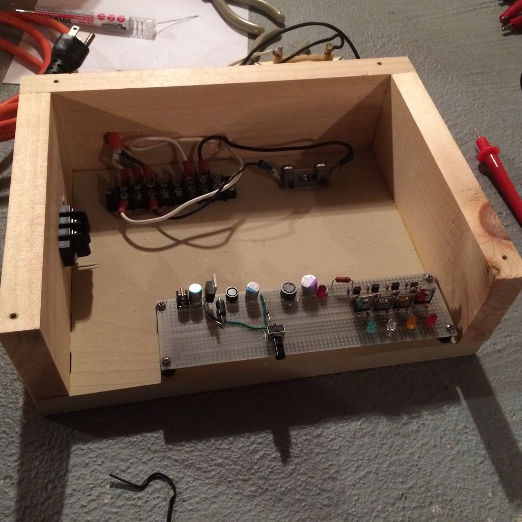
And here's all the banana jacks and so forth. It's mostly wired up now, and I'll stick some common-value resistors and capacitors across the central bunch of jacks so I can build circuits easily just using jumper cables.
[img
1024]http://i234.photobucket.com/albums/ee25 ... ygw3je.jpg[/img]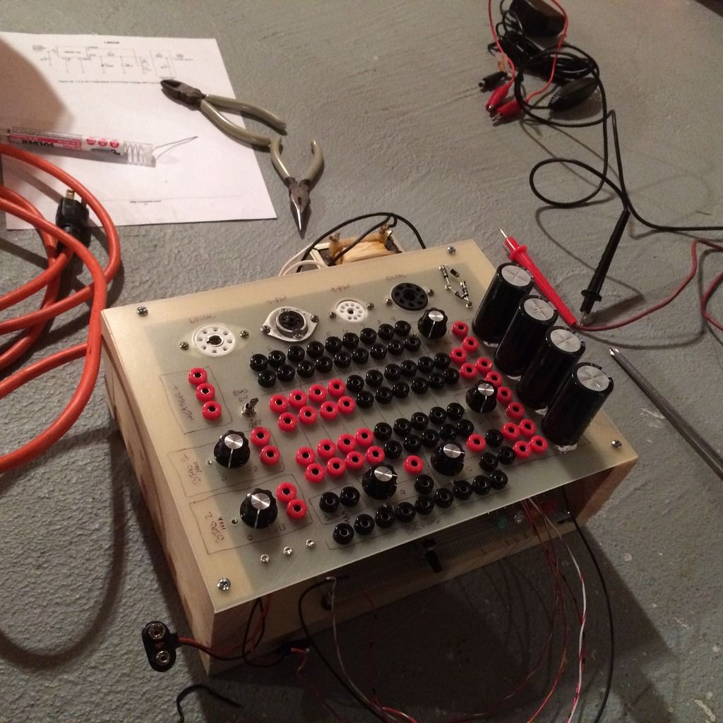
Re: weirdo tubes amp
Sorry for the apparent lack of interest, I think it may beyond some of us here. (me at least)
Sounds like a fascinating project.
Sounds like a fascinating project.
Tom
Don't let that smoke out!
Don't let that smoke out!
Re: weirdo tubes amp
No worries, this thread is mostly a build diary at this point, and I only think I know what I'm doing so I'm sure I'll be begging for help on something or another soon...